Oled Displaying imagessqw
  In this project an SPI OLED (128 X 64) monochrome display is used
  along with arduino to display images
  For that the images were converted into HEX code
  Adafruit SSD1306 library was used for this purpose
Clock and Calendar on Raspberry Pi using Java
 This is the tutorial for displaying clock and calendar on Raspberry Pi 3b+
 along with weather updates  using a java and
   3.5 inch TFT arduino shied
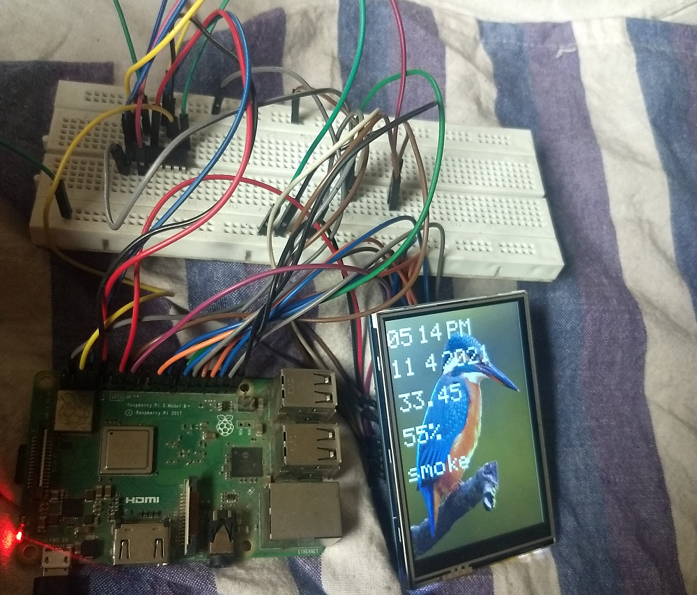
  For this project I have used   Raspberry Pi 3B+ module
  3.5 inch TFT arduino shield having controller    ili9486
   and connecting wires


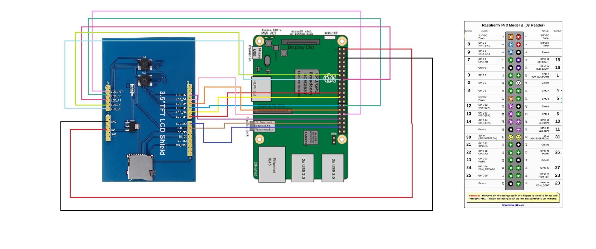
  The pin connection is based on wiring4j


  The  diagram shows how to connect Raspberry Pi pins with tft arduino shield
 After the connections are done.

 Download the pi4j Library  with the help of the link given below


 pi4j library
  Install   openjdk11 on your raspberry pi..the same jdk version should be on your laptop
  You can refer the link given below
  install openjdk11


  Download the following softwares on your laptop
   WinSCP (for transferring files from laptop to raspi)
   RealVNC (for virtually connecting laptop and raspi)


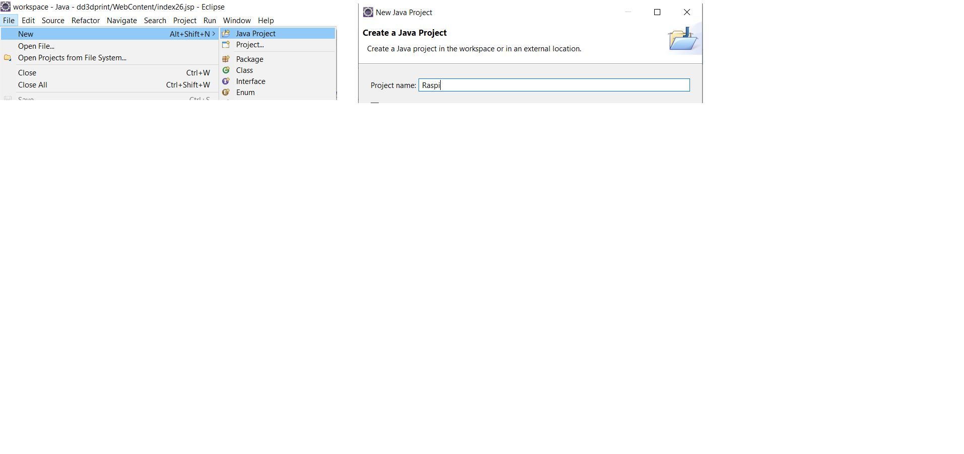
  Open Eclipse ide on laptop

  File --> New --> Java Project-->In Project name --> Raspi -->Finish

  Add all  the downloaded  pi4j jarfiles in the project
  Open the Project


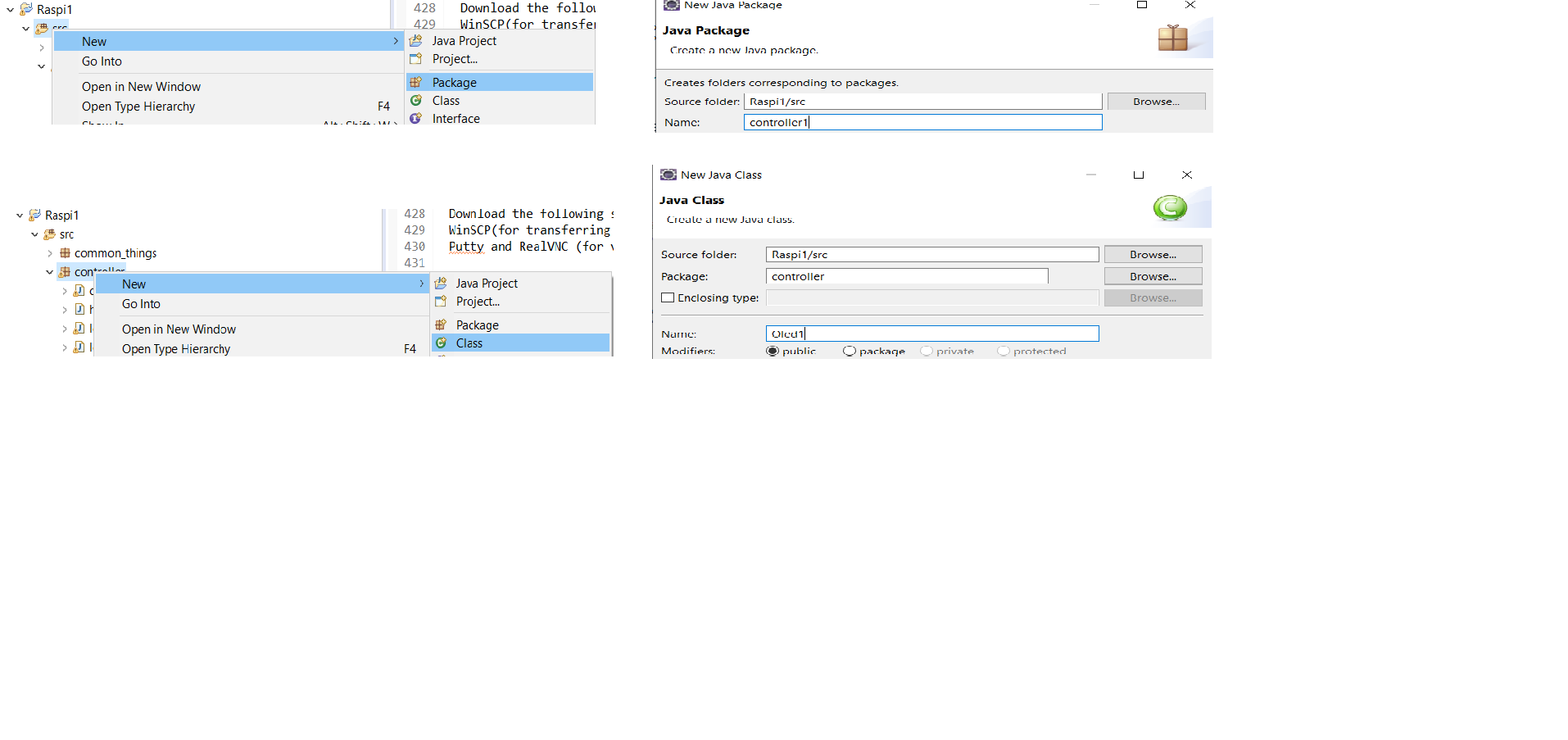
  src --> New -->Package -->controller-->Finish

  controller--> New --> Class --> TFT -->Finish
  Refer the code given in the link and use that in your   class

  github link

  Scroll to the TFT.java -->Right click--> Run as-->Java Application

  The console will show error ignore it for now as we are going to transfer our file to Raspberry Pi

  Right Click on the Raspi Project-->Export -->Java--> Runnable JAR file -->Next

  Launch configuration -->   TFT -Raspi

  Export designation --> C:\User...\tft96.jar
  Open the    WinSCP software
  login Screen will appear

  Host Name : 192.168.0.21  WinSCP  (your assigned ip address)
  User Name :   pi (your assigned username) Password:  123456  (your assigned password)
  Drag the file  tft96.jar and bird.csv   from laptop to Raspberry Pi
  Open the   RealVNC Software


  File -->New Connection
  VNC Server : 192.168.0.21  192.168.0.21  (ip address of pi)
  Name :   pi@21 click OK

  A new window will appear click on the icon pi@21
  Username:     Pi  (your assigned username for pi)
  Password :  123456 (your assigned password for pi)
   You will see Raspberry Pi   screen on VNC
   Click on the Raspberry Pi   icon --->Accessories -->Terminal


    After it opens type

                      cd Desktop

                      ls
                      sudo java -jar tft96.jar


                     Note: Type the name of your jar file instead of tft96.jar
                                                  Press Enter
Oled on Raspberrypi using java
  This is the tutorial for interfacing oled on Raspberry pi using java
  Most tutorials on the web are python based  so I thought why not
  give it a try using java


  For this project I have used   Raspberry Pi 3B+ module
  6 pin oled (128x64) and connecting wires


  The pin connection is based on wiring4j
  Please visit pi4j website for downloading the libraries and pin description

 Download the pi4j Library for the same with the help of the link given below


 pi4j library
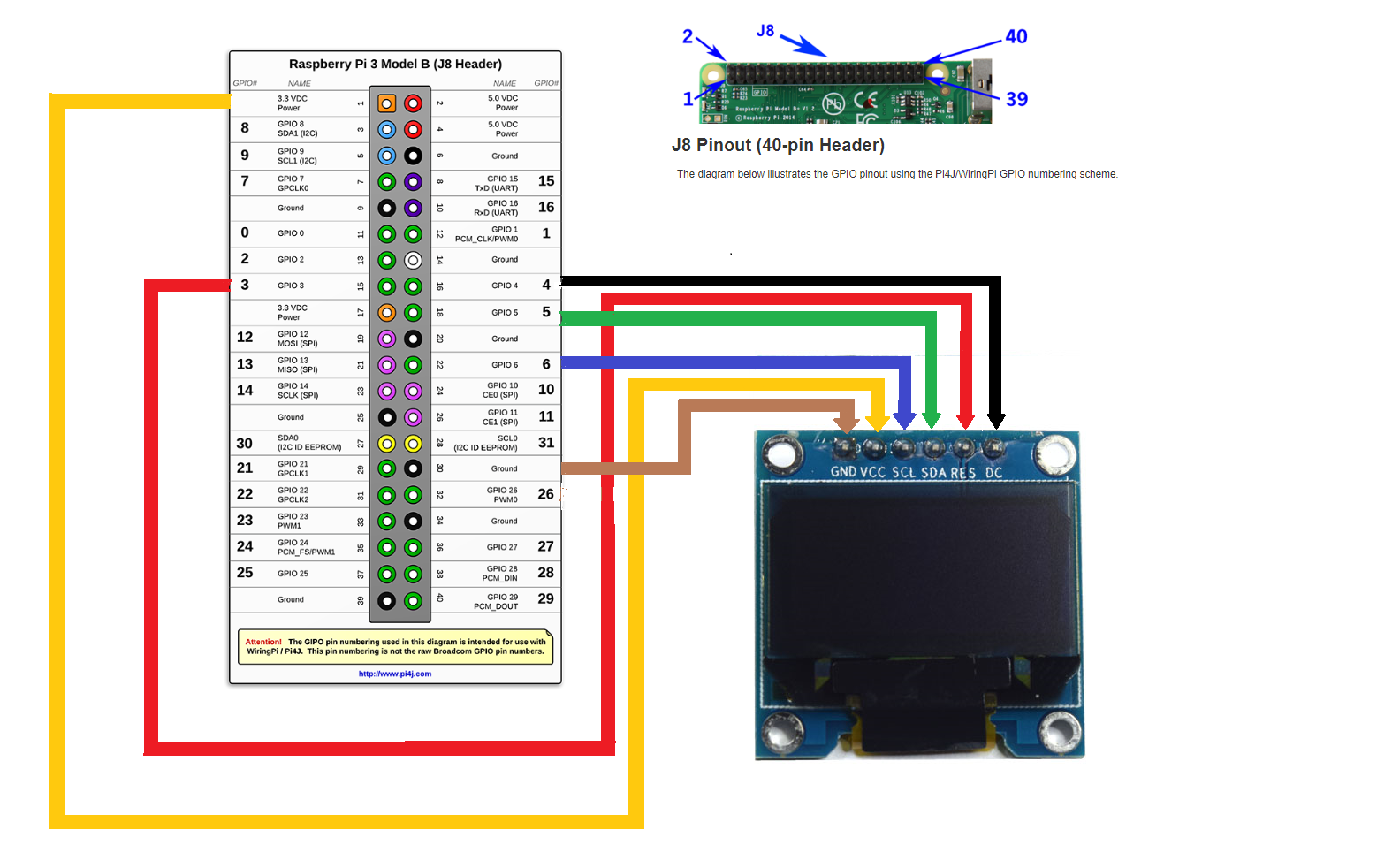
  Its a prerequisite that you visit tutorials on oled
  Install   openjdk11 on your raspberry pi..the same jdk version should be on your laptop
  You can refer the link given below
  install openjdk11


  Download the following softwares on your laptop
   WinSCP (for transferring files from laptop to raspi)
   RealVNC (for virtually connecting laptop and raspi)


  Open Eclipse ide on laptop

  File --> New --> Java Project-->In Project name --> Raspi -->Finish

  Open the Project


  src --> New -->Package -->controller1-->Finish

  controller1--> New --> Class --> Oled -->Finish

  Refer the code given below and use that in your   class


  Scroll to the Oled.java -->Right click--> Run as-->Java Application

  The console will show error ignore it for now as we are going to transfer our file to Raspberry Pi

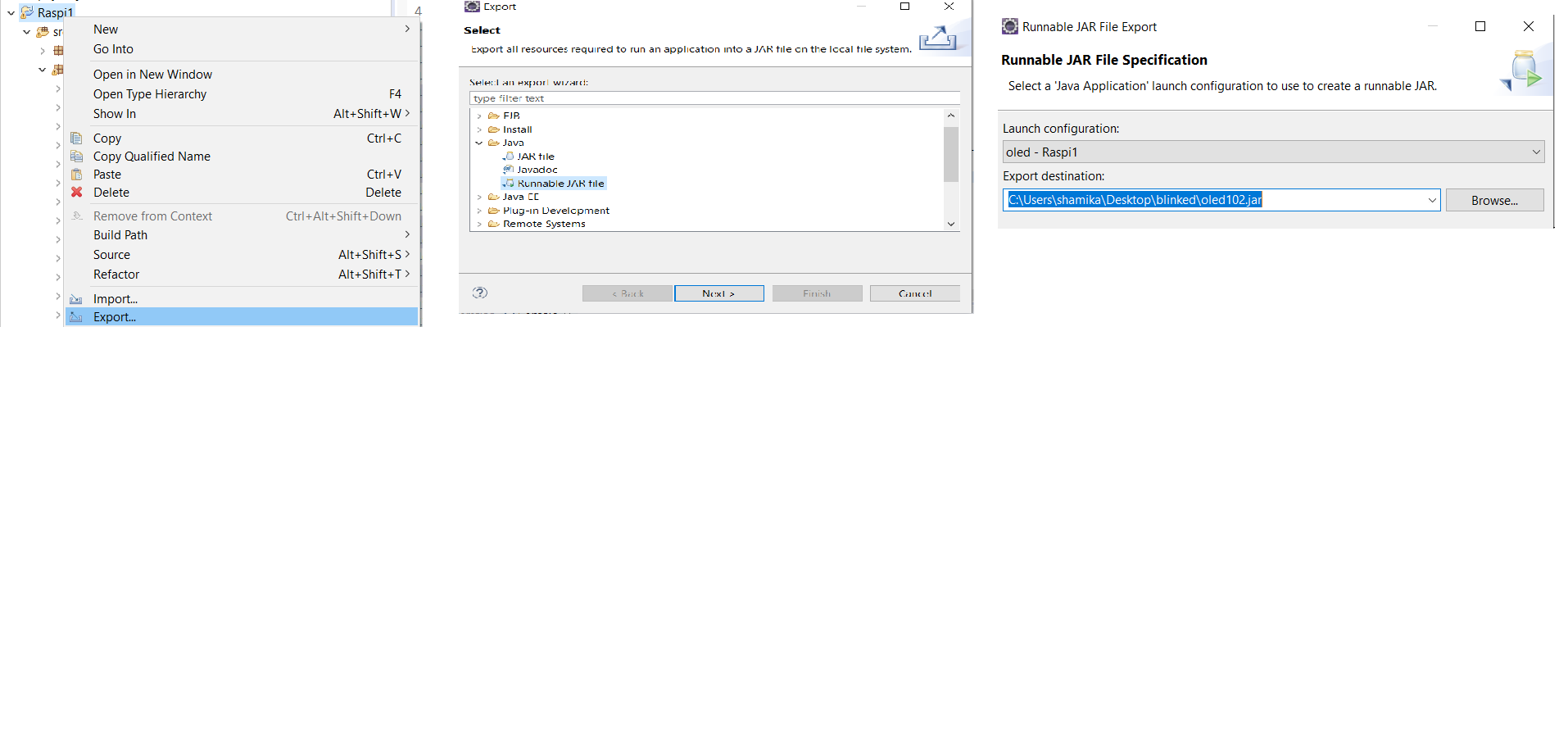
  Right Click on the Raspi Project-->Export -->Java--> Runnable JAR file -->Next

  Launch configuration -->   oled -Raspi

  Export designation --> C:\User...\oled102.jar

package controller;
import java.io.InputStream;
import java.sql.Connection;
import java.sql.PreparedStatement;
import java.sql.ResultSet;
import java.sql.SQLException;
import java.util.concurrent.TimeUnit;
import com.pi4j.io.gpio.GpioController;
import com.pi4j.io.gpio.GpioFactory;
import com.pi4j.io.gpio.GpioPinDigitalOutput;
import com.pi4j.io.gpio.RaspiPin;
public class oled {
static int count=0;
static GpioController gpioController= GpioFactory.getInstance();
static GpioPinDigitalOutput DC= gpioController.provisionDigitalOutputPin(RaspiPin.GPIO_04);
static GpioPinDigitalOutput SDK= gpioController.provisionDigitalOutputPin(RaspiPin.GPIO_05);
static GpioPinDigitalOutput SCLK= gpioController.provisionDigitalOutputPin(RaspiPin.GPIO_06);
static GpioPinDigitalOutput RESET= gpioController.provisionDigitalOutputPin(RaspiPin.GPIO_03);
static GpioPinDigitalOutput led= gpioController.provisionDigitalOutputPin(RaspiPin.GPIO_02);
static String SSD1306_PIXEL_WIDTH=inttohex(128);
static String SSD1306_PIXEL_HEIGHT=inttohex(64);
static String SSD1306_PAGE_COUNT=inttohex(8);
static String SSD1306_PAGE_HEIGHT= inttohex(2);
//static String SSD1306_SEGMENT_COUNT= inttohex(7808);//7808 //check
static String SSD1306_FONT_WIDTH=inttohex(1);
//fundamental commands
static String SSD1306_SET_CONTRAST =inttohex(129);
static String SSD1306_CONTRAST_DEFAULT = inttohex(127); // 0b01111111
static String SSD1306_DISPLAY =inttohex(164); // 0b10100100
static String SSD1306_DISPLAY_RESET =inttohex(164); // SSD1306_DISPLAY
static String SSD1306_DISPLAY_ALLON =inttohex(165); // SSD1306_DISPLAY | 0b01
static String SSD1306_DISPLAY_NORMAL =inttohex(166); // SSD1306_DISPLAY | 0b10
static String SSD1306_DISPLAY_INVERSE =inttohex(166); // SSD1306_DISPLAY | 0b11
static String SSD1306_DISPLAY_SLEEP =inttohex(174); // SSD1306_DISPLAY | 0b1110
static String SSD1306_DISPLAY_ON =inttohex(175); // SSD1306_DISPLAY | 0b1111
static String SSD1306_DISPLAYALLON_RESUME =inttohex(164); // 0xA4
// addressing
static String SSD1306_ADDRESSING = inttohex(32); // 0x20
static String SSD1306_ADDRESSING_HORIZONTAL = inttohex(0); //
static String SSD1306_ADDRESSING_VERTICAL = inttohex(1); //
static String SSD1306_ADDRESSING_PAGE = inttohex(2); //
static String SSD1306_SET_COLUMN = inttohex(33); // 0x21
static String SSD1306_SET_PAGE = inttohex(34); // 0x22
// hardware configuration
static String SSD1306_SET_START_LINE = inttohex(64); // 0x40
static String SSD1306_START_LINE_DEFAULT = inttohex(0); //
static String SSD1306_SET_SEG_SCAN = inttohex(160); // 0xA0
static String SSD1306_SET_SEG_SCAN_DEFAULT = inttohex(160); // SSD1306_SET_SEG_SCAN | 0b00
static String SSD1306_SET_SEG_SCAN_REVERSE = inttohex(161); //SSD1306_SET_SEG_SCAN | 0b01
static String SSD1306_SET_MULTIPLEX_RATIO = inttohex(168); //0b10101000 // 0xA8
static String SSD1306_MULTIPLEX_RATIO_DEFAULT = inttohex(63); // 0b00111111
static String SSD1306_SET_COM_SCAN = inttohex(192); // 0xC0
static String SSD1306_SET_COM_SCAN_DEFAULT = inttohex(192); //SSD1306_SET_COM_SCAN | 0b0000
static String SSD1306_SET_COM_SCAN_REVERSE = inttohex(200); //SSD1306_SET_COM_SCAN | 0b1000
static String SSD1306_SET_DISPLAY_OFFSET = inttohex(211); // // 0xD3
static String SSD1306_DISPLAY_OFFSET_DEFAULT = inttohex(0); // 0b00000000
static String SSD1306_SET_COM_PINS = inttohex(218); //// 0xDA
static String SSD1306_COM_PINS_DEFAULT = inttohex(18); //
// timing and driving
static String SSD1306_SET_CLOCK_FREQUENCY = inttohex(213); // 0xD5
static String SSD1306_CLOCK_FREQUENCY_DEFAULT = inttohex(128); //
static String SSD1306_SET_PRECHARGE = inttohex(217); //0xD9
static String SSD1306_PRECHARGE_DEFAULT = inttohex(34); //
static String SSD1306_SET_VCOMH_DESELECT = inttohex(219); // 0xDB
static String SSD1306_VCOMH_DESELECT_DEFAULT = inttohex(32); //
static String SSD1306_SET_CHARGE_PUMP = inttohex(141); // 0x8D
static String SSD1306_CHARGE_PUMP_ENABLE = inttohex(20); //
static String SSD1306_NOP = inttohex(227); //0xE3
public static void main(String[] args)
{
System.out.println("oled code started");
led.high();
try {
TimeUnit.MICROSECONDS.sleep(1000000);
} catch (InterruptedException e) {
// TODO Auto-generated catch block
e.printStackTrace();
}
led.low();
try {
TimeUnit.MICROSECONDS.sleep(1000000);
} catch (InterruptedException e) {
// TODO Auto-generated catch block
e.printStackTrace();
}
OledInit();
System.out.println("oled initialization done");
oledClear();
System.out.println("oled cleared");
//oledClearAgain();
//System.out.println("oled cleared again");
while(true)
{
oledWriteString(1,1,"hello world");
}
}
public static String inttohex(int data)
{
String val2= Integer.toHexString(data);
if(val2.equals("0"))
val2="00";
if(val2.equals("1"))
val2="01";
if(val2.equals("2"))
val2="02";
if(val2.equals("3"))
val2="03";
if(val2.equals("4"))
val2="04";
if(val2.equals("5"))
val2="05";
if(val2.equals("6"))
val2="06";
if(val2.equals("7"))
val2="07";
if(val2.equals("8"))
val2="08";
if(val2.equals("9"))
val2="09";
if(val2.equals("a"))
val2="0a";
if(val2.equals("b"))
val2="0b";
if(val2.equals("c"))
val2="0c";
if(val2.equals("d"))
val2="0d";
if(val2.equals("e"))
val2="0e";
if(val2.equals("f"))
val2="0f";
return val2;
}
static void oledWriteCmd(String ledcmd)
{
DC.low();
String part1=ledcmd.substring(0, 1);
String part2=ledcmd.substring(1, 2);
//System.out.println("part1 is : "+part1);
//System.out.println("part2 is : "+part2);
String finalpart1=intto4bit(part1);
String finalpart2=intto4bit(part2);
String finalpart= finalpart1+ finalpart2;
int countcmd=0;
while(countcmd<8)
{
int sdkcmd= Integer.parseInt(finalpart.substring(countcmd, countcmd+1));
//System.out.println("sdk is : "+sdkdata);
if(sdkcmd==1)
{
SDK.high();
}
else
{
SDK.low();
}
SCLK.high();
try {
TimeUnit.MICROSECONDS.sleep(100);
} catch (InterruptedException e) {
// TODO Auto-generated catch block
e.printStackTrace();
}
SCLK.low();
try {
TimeUnit.MICROSECONDS.sleep(100);
} catch (InterruptedException e) {
// TODO Auto-generated catch block
e.printStackTrace();
}
countcmd++;
}
}
static void oledWriteData(String leddata)
{
DC.high();
String part1=leddata.substring(0, 1);
String part2=leddata.substring(1, 2);
//System.out.println("part1 is : "+part1);
//System.out.println("part2 is : "+part2);
String finalpart1=intto4bit(part1);
String finalpart2=intto4bit(part2);
String finalpart= finalpart1+ finalpart2;
count=0;
while(count<8)
{
int sdkdata= Integer.parseInt(finalpart.substring(count, count+1));
//System.out.println("sdk is : "+sdkdata);
if(sdkdata==1)
{
SDK.high();
led.high();
//System.out.println("reached here sdkdata high");
}
else
{
SDK.low();
led.low();
//System.out.println("reached here sdk data low");
}
SCLK.high();
try {
TimeUnit.MICROSECONDS.sleep(200);
} catch (InterruptedException e) {
// TODO Auto-generated catch block
e.printStackTrace();
}
SCLK.low();
try {
TimeUnit.MICROSECONDS.sleep(200);
} catch (InterruptedException e) {
// TODO Auto-generated catch block
e.printStackTrace();
}
count++;
}
}
static void OledInit()
{
RESET.low();
try {
TimeUnit.MICROSECONDS.sleep(5);
} catch (InterruptedException e) {
// TODO Auto-generated catch block
e.printStackTrace();
}
RESET.high();
oledWriteCmd(SSD1306_SET_MULTIPLEX_RATIO);
System.out.println("reached here 1");
oledWriteCmd(SSD1306_MULTIPLEX_RATIO_DEFAULT);
System.out.println("reached here 2");
oledWriteCmd(SSD1306_DISPLAY_RESET);
System.out.println("reached here 3");
oledWriteCmd(SSD1306_SET_DISPLAY_OFFSET);
System.out.println("reached here 4");
oledWriteCmd(SSD1306_DISPLAY_OFFSET_DEFAULT);
System.out.println("reached here 5");
oledWriteCmd(SSD1306_START_LINE_DEFAULT); //check
System.out.println("reached here 6");
oledWriteCmd(SSD1306_SET_SEG_SCAN_REVERSE);
System.out.println("reached here 7");
oledWriteCmd(SSD1306_SET_COM_SCAN_REVERSE);
System.out.println("reached here 8");
oledWriteCmd(SSD1306_SET_COM_PINS);
oledWriteCmd(SSD1306_COM_PINS_DEFAULT);
oledWriteCmd(SSD1306_SET_CONTRAST);
String var1= inttohex(255);
oledWriteCmd(var1);
String var2= inttohex(164);
oledWriteCmd(var2);
String var3= inttohex(166);
oledWriteCmd(var3);
oledWriteCmd(SSD1306_SET_CLOCK_FREQUENCY);
String var4= inttohex(242);
oledWriteCmd(var4);
oledWriteCmd(SSD1306_SET_CHARGE_PUMP);
oledWriteCmd(SSD1306_CHARGE_PUMP_ENABLE);
oledWriteCmd(SSD1306_SET_PRECHARGE);
oledWriteCmd(SSD1306_PRECHARGE_DEFAULT);
oledWriteCmd(SSD1306_SET_VCOMH_DESELECT);
oledWriteCmd(SSD1306_VCOMH_DESELECT_DEFAULT);
oledWriteCmd(SSD1306_DISPLAY_ON);
oledWriteCmd(SSD1306_DISPLAY_RESET);
System.out.println("completed initialization");
}
static void oledClear() {
oledWriteCmd(SSD1306_DISPLAY_SLEEP);
oledWriteCmd(SSD1306_ADDRESSING);
oledWriteCmd(SSD1306_ADDRESSING_HORIZONTAL);
// String var5=inttohex(0);
for(int i=0; i<1024; i++)
oledWriteData(inttohex(0));
oledWriteCmd(SSD1306_ADDRESSING);
oledWriteCmd(SSD1306_ADDRESSING_PAGE);
oledWriteCmd(SSD1306_DISPLAY_ON);
oledWriteCmd(SSD1306_DISPLAY_RESET);
}
static void oledSetXY(int x, int y) {
oledWriteCmd(SSD1306_SET_COLUMN);
String var6=inttohex(x);
String var7=inttohex(y);
oledWriteCmd(var6);
oledWriteCmd(inttohex(127));
oledWriteCmd(SSD1306_SET_PAGE);
oledWriteCmd(var7);
oledWriteCmd(inttohex(63));
}
static void oledWriteChar(String string)
{
switch(string)
{
case "!":
oledWriteData(inttohex(0));
oledWriteData(inttohex(0));
oledWriteData(inttohex(95));
oledWriteData(inttohex(0));
oledWriteData(inttohex(0));
break;
/*
case '"':
oledWriteData(inttohex(0));
oledWriteData(inttohex(7));
oledWriteData(inttohex(0));
oledWriteData(inttohex(7));
oledWriteData(inttohex(0));
break;
*/
case "#":
oledWriteData(inttohex(20));
oledWriteData(inttohex(127));
oledWriteData(inttohex(20));
oledWriteData(inttohex(127));
oledWriteData(inttohex(20));
break;
case "$":
oledWriteData(inttohex(36));
oledWriteData(inttohex(42));
oledWriteData(inttohex(127));
oledWriteData(inttohex(42));
oledWriteData(inttohex(18));
break;
case "%":
oledWriteData(inttohex(35));
oledWriteData(inttohex(19));
oledWriteData(inttohex(8));
oledWriteData(inttohex(100));
oledWriteData(inttohex(98));
break;
case "&":
oledWriteData(inttohex(54));
oledWriteData(inttohex(73));
oledWriteData(inttohex(85));
oledWriteData(inttohex(34));
oledWriteData(inttohex(80));
break;
case "(":
oledWriteData(inttohex(0));
oledWriteData(inttohex(28));
oledWriteData(inttohex(34));
oledWriteData(inttohex(65));
oledWriteData(inttohex(0));
break;
case ")":
oledWriteData(inttohex(0));
oledWriteData(inttohex(65));
oledWriteData(inttohex(34));
oledWriteData(inttohex(28));
oledWriteData(inttohex(0));
break;
case "*":
oledWriteData(inttohex(20));
oledWriteData(inttohex(8));
oledWriteData(inttohex(62));
oledWriteData(inttohex(8));
oledWriteData(inttohex(20));
break;
case "+":
oledWriteData(inttohex(8));
oledWriteData(inttohex(8));
oledWriteData(inttohex(62));
oledWriteData(inttohex(8));
oledWriteData(inttohex(8));
break;
case ",":
oledWriteData(inttohex(0));
oledWriteData(inttohex(80));
oledWriteData(inttohex(48));
oledWriteData(inttohex(0));
oledWriteData(inttohex(0));
break;
case "-":
oledWriteData(inttohex(8));
oledWriteData(inttohex(8));
oledWriteData(inttohex(8));
oledWriteData(inttohex(8));
oledWriteData(inttohex(8));
break;
case ".":
oledWriteData(inttohex(0));
oledWriteData(inttohex(96));
oledWriteData(inttohex(96));
oledWriteData(inttohex(0));
oledWriteData(inttohex(0));
break;
case "/":
oledWriteData(inttohex(32));
oledWriteData(inttohex(16));
oledWriteData(inttohex(8));
oledWriteData(inttohex(4));
oledWriteData(inttohex(2));
break;
case "0":
oledWriteData(inttohex(62));
oledWriteData(inttohex(81));
oledWriteData(inttohex(73));
oledWriteData(inttohex(69));
oledWriteData(inttohex(62));
break;
case "1":
oledWriteData(inttohex(0));
oledWriteData(inttohex(66));
oledWriteData(inttohex(127));
oledWriteData(inttohex(64));
oledWriteData(inttohex(0));
break;
case "2":
oledWriteData(inttohex(0));
oledWriteData(inttohex(66));
oledWriteData(inttohex(127));
oledWriteData(inttohex(64));
oledWriteData(inttohex(0));
break;
case "3":
oledWriteData(inttohex(33));
oledWriteData(inttohex(65));
oledWriteData(inttohex(69));
oledWriteData(inttohex(75));
oledWriteData(inttohex(49));
break;
case "4":
oledWriteData(inttohex(24));
oledWriteData(inttohex(20));
oledWriteData(inttohex(18));
oledWriteData(inttohex(127));
oledWriteData(inttohex(16));
break;
case "5":
oledWriteData(inttohex(39));
oledWriteData(inttohex(69));
oledWriteData(inttohex(69));
oledWriteData(inttohex(69));
oledWriteData(inttohex(57));
break;
case "6":
oledWriteData(inttohex(60));
oledWriteData(inttohex(74));
oledWriteData(inttohex(73));
oledWriteData(inttohex(73));
oledWriteData(inttohex(48));
break;
case "7":
oledWriteData(inttohex(1));
oledWriteData(inttohex(113));
oledWriteData(inttohex(9));
oledWriteData(inttohex(5));
oledWriteData(inttohex(3));
break;
case "8":
oledWriteData(inttohex(54));
oledWriteData(inttohex(73));
oledWriteData(inttohex(73));
oledWriteData(inttohex(73));
oledWriteData(inttohex(54));
break;
case "9":
oledWriteData(inttohex(6));
oledWriteData(inttohex(73));
oledWriteData(inttohex(73));
oledWriteData(inttohex(41));
oledWriteData(inttohex(30));
break;
case ":":
oledWriteData(inttohex(0));
oledWriteData(inttohex(54));
oledWriteData(inttohex(54));
oledWriteData(inttohex(0));
oledWriteData(inttohex(0));
break;
case ";":
oledWriteData(inttohex(0));
oledWriteData(inttohex(86));
oledWriteData(inttohex(54));
oledWriteData(inttohex(0));
oledWriteData(inttohex(0));
break;
case "<":
oledWriteData(inttohex(8));
oledWriteData(inttohex(20));
oledWriteData(inttohex(34));
oledWriteData(inttohex(65));
oledWriteData(inttohex(0));
break;
case "=":
oledWriteData(inttohex(20));
oledWriteData(inttohex(20));
oledWriteData(inttohex(20));
oledWriteData(inttohex(20));
oledWriteData(inttohex(20));
break;
case ">":
oledWriteData(inttohex(0));
oledWriteData(inttohex(65));
oledWriteData(inttohex(34));
oledWriteData(inttohex(20));
oledWriteData(inttohex(8));
break;
case "?":
oledWriteData(inttohex(2));
oledWriteData(inttohex(1));
oledWriteData(inttohex(81));
oledWriteData(inttohex(9));
oledWriteData(inttohex(6));
break;
case "@":
oledWriteData(inttohex(50));
oledWriteData(inttohex(73));
oledWriteData(inttohex(121));
oledWriteData(inttohex(65));
oledWriteData(inttohex(62));
break;
case "A":
oledWriteData(inttohex(126));
oledWriteData(inttohex(17));
oledWriteData(inttohex(17));
oledWriteData(inttohex(17));
oledWriteData(inttohex(126));
break;
case "B":
oledWriteData(inttohex(127));
oledWriteData(inttohex(73));
oledWriteData(inttohex(73));
oledWriteData(inttohex(73));
oledWriteData(inttohex(54));
break;
case "C":
oledWriteData(inttohex(62));
oledWriteData(inttohex(65));
oledWriteData(inttohex(65));
oledWriteData(inttohex(65));
oledWriteData(inttohex(34));
break;
case "D":
oledWriteData(inttohex(127));
oledWriteData(inttohex(65));
oledWriteData(inttohex(65));
oledWriteData(inttohex(34));
oledWriteData(inttohex(28));
break;
case "E":
oledWriteData(inttohex(127));
oledWriteData(inttohex(73));
oledWriteData(inttohex(73));
oledWriteData(inttohex(73));
oledWriteData(inttohex(65));
break;
case "F":
oledWriteData(inttohex(127));
oledWriteData(inttohex(9));
oledWriteData(inttohex(9));
oledWriteData(inttohex(9));
oledWriteData(inttohex(1));
break;
case "G":
oledWriteData(inttohex(62));
oledWriteData(inttohex(65));
oledWriteData(inttohex(73));
oledWriteData(inttohex(73));
oledWriteData(inttohex(122));
break;
case "H":
oledWriteData(inttohex(127));
oledWriteData(inttohex(8));
oledWriteData(inttohex(8));
oledWriteData(inttohex(8));
oledWriteData(inttohex(127));
break;
case "I":
oledWriteData(inttohex(0));
oledWriteData(inttohex(65));
oledWriteData(inttohex(127));
oledWriteData(inttohex(65));
oledWriteData(inttohex(0));
break;
case "J":
oledWriteData(inttohex(32));
oledWriteData(inttohex(64));
oledWriteData(inttohex(65));
oledWriteData(inttohex(63));
oledWriteData(inttohex(1));
break;
case "K":
oledWriteData(inttohex(127));
oledWriteData(inttohex(8));
oledWriteData(inttohex(20));
oledWriteData(inttohex(34));
oledWriteData(inttohex(65));
break;
case "L":
oledWriteData(inttohex(127));
oledWriteData(inttohex(64));
oledWriteData(inttohex(64));
oledWriteData(inttohex(64));
oledWriteData(inttohex(64));
break;
case "M":
oledWriteData(inttohex(127));
oledWriteData(inttohex(2));
oledWriteData(inttohex(12));
oledWriteData(inttohex(2));
oledWriteData(inttohex(127));
break;
case "N":
oledWriteData(inttohex(127));
oledWriteData(inttohex(4));
oledWriteData(inttohex(8));
oledWriteData(inttohex(16));
oledWriteData(inttohex(127));
break;
case "O":
oledWriteData(inttohex(62));
oledWriteData(inttohex(65));
oledWriteData(inttohex(65));
oledWriteData(inttohex(65));
oledWriteData(inttohex(62));
break;
case "P":
oledWriteData(inttohex(127));
oledWriteData(inttohex(9));
oledWriteData(inttohex(9));
oledWriteData(inttohex(9));
oledWriteData(inttohex(6));
break;
case "Q":
oledWriteData(inttohex(62));
oledWriteData(inttohex(65));
oledWriteData(inttohex(81));
oledWriteData(inttohex(33));
oledWriteData(inttohex(94));
break;
case "R":
oledWriteData(inttohex(127));
oledWriteData(inttohex(9));
oledWriteData(inttohex(25));
oledWriteData(inttohex(41));
oledWriteData(inttohex(70));
break;
case "S":
oledWriteData(inttohex(70));
oledWriteData(inttohex(73));
oledWriteData(inttohex(73));
oledWriteData(inttohex(73));
oledWriteData(inttohex(49));
break;
case "T":
oledWriteData(inttohex(1));
oledWriteData(inttohex(1));
oledWriteData(inttohex(127));
oledWriteData(inttohex(1));
oledWriteData(inttohex(1));
break;
case "U":
oledWriteData(inttohex(63));
oledWriteData(inttohex(64));
oledWriteData(inttohex(64));
oledWriteData(inttohex(64));
oledWriteData(inttohex(63));
break;
case "V":
oledWriteData(inttohex(31));
oledWriteData(inttohex(32));
oledWriteData(inttohex(64));
oledWriteData(inttohex(32));
oledWriteData(inttohex(31));
break;
case "W":
oledWriteData(inttohex(63));
oledWriteData(inttohex(64));
oledWriteData(inttohex(56));
oledWriteData(inttohex(64));
oledWriteData(inttohex(63));
break;
case "X":
oledWriteData(inttohex(99));
oledWriteData(inttohex(20));
oledWriteData(inttohex(8));
oledWriteData(inttohex(20));
oledWriteData(inttohex(99));
break;
case "Y":
oledWriteData(inttohex(7));
oledWriteData(inttohex(8));
oledWriteData(inttohex(112));
oledWriteData(inttohex(8));
oledWriteData(inttohex(7));
break;
case "Z":
oledWriteData(inttohex(97));
oledWriteData(inttohex(81));
oledWriteData(inttohex(73));
oledWriteData(inttohex(69));
oledWriteData(inttohex(67));
break;
case "[":
oledWriteData(inttohex(0));
oledWriteData(inttohex(127));
oledWriteData(inttohex(65));
oledWriteData(inttohex(65));
oledWriteData(inttohex(0));
break;
case "]":
oledWriteData(inttohex(0));
oledWriteData(inttohex(65));
oledWriteData(inttohex(65));
oledWriteData(inttohex(127));
oledWriteData(inttohex(0));
break;
case "^":
oledWriteData(inttohex(4));
oledWriteData(inttohex(2));
oledWriteData(inttohex(1));
oledWriteData(inttohex(2));
oledWriteData(inttohex(4));
break;
case "_":
oledWriteData(inttohex(64));
oledWriteData(inttohex(64));
oledWriteData(inttohex(64));
oledWriteData(inttohex(64));
oledWriteData(inttohex(64));
break;
case "`":
oledWriteData(inttohex(0));
oledWriteData(inttohex(1));
oledWriteData(inttohex(2));
oledWriteData(inttohex(4));
oledWriteData(inttohex(0));
break;
case "a":
oledWriteData(inttohex(32)); //0x20
oledWriteData(inttohex(84)); //0x54
oledWriteData(inttohex(84)); //0x54
oledWriteData(inttohex(84)); //0x54
oledWriteData(inttohex(120)); //0x78
break;
case "b":
oledWriteData(inttohex(127));
oledWriteData(inttohex(72));
oledWriteData(inttohex(68));
oledWriteData(inttohex(68));
oledWriteData(inttohex(56));
break;
case "c":
oledWriteData(inttohex(56));
oledWriteData(inttohex(68));
oledWriteData(inttohex(68));
oledWriteData(inttohex(68));
oledWriteData(inttohex(32));
break;
case "d":
oledWriteData(inttohex(56));
oledWriteData(inttohex(68));
oledWriteData(inttohex(68));
oledWriteData(inttohex(72));
oledWriteData(inttohex(127));
break;
case "e":
oledWriteData(inttohex(56));
oledWriteData(inttohex(84));
oledWriteData(inttohex(84));
oledWriteData(inttohex(84));
oledWriteData(inttohex(24));
break;
case "f":
oledWriteData(inttohex(8));
oledWriteData(inttohex(126));
oledWriteData(inttohex(9));
oledWriteData(inttohex(1));
oledWriteData(inttohex(2));
break;
case "g":
oledWriteData(inttohex(12));
oledWriteData(inttohex(82));
oledWriteData(inttohex(82));
oledWriteData(inttohex(82));
oledWriteData(inttohex(62));
break;
case "h":
oledWriteData(inttohex(127));
oledWriteData(inttohex(8));
oledWriteData(inttohex(4));
oledWriteData(inttohex(4));
oledWriteData(inttohex(120));
break;
case "i":
oledWriteData(inttohex(0));
oledWriteData(inttohex(68));
oledWriteData(inttohex(125));
oledWriteData(inttohex(64));
oledWriteData(inttohex(0));
break;
case "j":
oledWriteData(inttohex(32));
oledWriteData(inttohex(64));
oledWriteData(inttohex(68));
oledWriteData(inttohex(61));
oledWriteData(inttohex(0));
break;
case "k":
oledWriteData(inttohex(127));
oledWriteData(inttohex(16));
oledWriteData(inttohex(40));
oledWriteData(inttohex(68));
oledWriteData(inttohex(0));
break;
case "l":
oledWriteData(inttohex(0));
oledWriteData(inttohex(65));
oledWriteData(inttohex(127));
oledWriteData(inttohex(64));
oledWriteData(inttohex(0));
break;
case "m":
oledWriteData(inttohex(124));
oledWriteData(inttohex(4));
oledWriteData(inttohex(24));
oledWriteData(inttohex(4));
oledWriteData(inttohex(120));
break;
case "n":
oledWriteData(inttohex(124));
oledWriteData(inttohex(8));
oledWriteData(inttohex(4));
oledWriteData(inttohex(4));
oledWriteData(inttohex(120));
break;
case "o":
oledWriteData(inttohex(56));
oledWriteData(inttohex(68));
oledWriteData(inttohex(68));
oledWriteData(inttohex(68));
oledWriteData(inttohex(56));
break;
case "p":
oledWriteData(inttohex(124));
oledWriteData(inttohex(20));
oledWriteData(inttohex(20));
oledWriteData(inttohex(20));
oledWriteData(inttohex(8));
break;
case "q":
oledWriteData(inttohex(8));
oledWriteData(inttohex(20));
oledWriteData(inttohex(20));
oledWriteData(inttohex(24));
oledWriteData(inttohex(124));
break;
case "r":
oledWriteData(inttohex(124));
oledWriteData(inttohex(8));
oledWriteData(inttohex(4));
oledWriteData(inttohex(4));
oledWriteData(inttohex(8));
break;
case "s":
oledWriteData(inttohex(72));
oledWriteData(inttohex(84));
oledWriteData(inttohex(84));
oledWriteData(inttohex(84));
oledWriteData(inttohex(32));
break;
case "t":
oledWriteData(inttohex(4));
oledWriteData(inttohex(63));
oledWriteData(inttohex(68));
oledWriteData(inttohex(64));
oledWriteData(inttohex(32));
break;
case "u":
oledWriteData(inttohex(60));
oledWriteData(inttohex(64));
oledWriteData(inttohex(64));
oledWriteData(inttohex(32));
oledWriteData(inttohex(124));
break;
case "v":
oledWriteData(inttohex(28));
oledWriteData(inttohex(32));
oledWriteData(inttohex(64));
oledWriteData(inttohex(32));
oledWriteData(inttohex(24));
break;
case "w":
oledWriteData(inttohex(60));
oledWriteData(inttohex(64));
oledWriteData(inttohex(48));
oledWriteData(inttohex(64));
oledWriteData(inttohex(60));
break;
case "x":
oledWriteData(inttohex(68));
oledWriteData(inttohex(40));
oledWriteData(inttohex(16));
oledWriteData(inttohex(40));
oledWriteData(inttohex(68));
break;
case "y":
oledWriteData(inttohex(12));
oledWriteData(inttohex(80));
oledWriteData(inttohex(80));
oledWriteData(inttohex(80));
oledWriteData(inttohex(60));
break;
case "z":
oledWriteData(inttohex(68));
oledWriteData(inttohex(100));
oledWriteData(inttohex(84));
oledWriteData(inttohex(76));
oledWriteData(inttohex(68));
break;
case "{":
oledWriteData(inttohex(0));
oledWriteData(inttohex(8));
oledWriteData(inttohex(54));
oledWriteData(inttohex(65));
oledWriteData(inttohex(0));
break;
case "|":
oledWriteData(inttohex(0));
oledWriteData(inttohex(0));
oledWriteData(inttohex(127));
oledWriteData(inttohex(0));
oledWriteData(inttohex(0));
break;
case "}":
oledWriteData(inttohex(0));
oledWriteData(inttohex(65));
oledWriteData(inttohex(54));
oledWriteData(inttohex(8));
oledWriteData(inttohex(0));
break;
}
}
static void oledWriteString(int x,int y,String characters)
{
for(int k=0;k <=characters.length();k++)
{
oledSetXY(x,y);
oledWriteChar(characters.substring(k, k+1));
x=x+7;
}
}
static String intto4bit(String part)
{
String convertedpart = null;
if(part.equals("0"))
{
convertedpart="0000";
}
if(part.equals("1"))
{
convertedpart="0001";
}
if(part.equals("2"))
{
convertedpart="0010";
}
if(part.equals("3"))
{
convertedpart="0011";
}
if(part.equals("4"))
{
convertedpart="0100";
}
if(part.equals("5"))
{
convertedpart="0101";
}
if(part.equals("6"))
{
convertedpart="0110";
}
if(part.equals("7"))
{
convertedpart="0111";
}
if(part.equals("8"))
{
convertedpart="1000";
}
if(part.equals("9"))
{
convertedpart="1001";
}
if(part.equals("a"))
{
convertedpart="1010";
}
if(part.equals("b"))
{
convertedpart="1011";
}
if(part.equals("c"))
{
convertedpart="1100";
}
if(part.equals("d"))
{
convertedpart="1101";
}
if(part.equals("e"))
{
convertedpart="1110";
}
if(part.equals("f"))
{
convertedpart="1111";
}
return convertedpart;
}
}
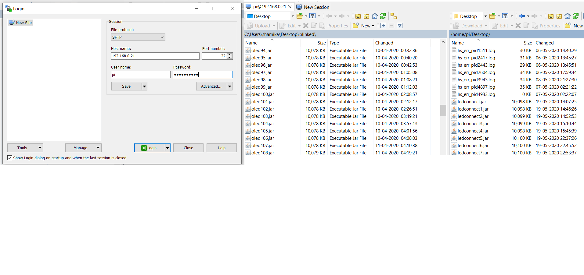
  Open the    WinSCP software
  login Screen will appear

  Host Name : 192.168.0.21  WinSCP  (your assigned ip address)
  User Name :   pi (your assigned username) Password:  123456  (your assigned password)
  Drag the file from laptop to Raspberry Pi

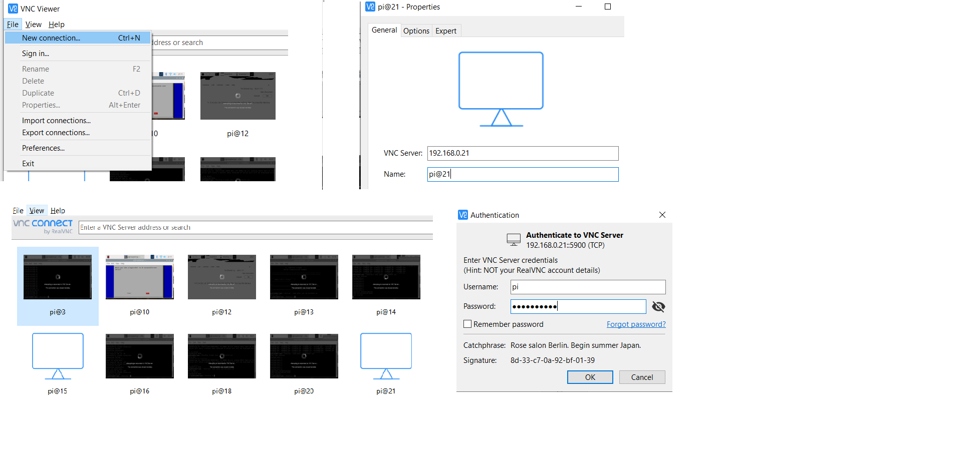
  Open the   RealVNC Software


  File -->New Connection
  VNC Server : 192.168.0.21  192.168.0.21  (ip address of pi)
  Name :   pi@21 click OK

  A new window will appear click on the icon pi@21
  Username:     Pi  (your assigned username for pi)
  Password :  123456 (your assigned password for pi)

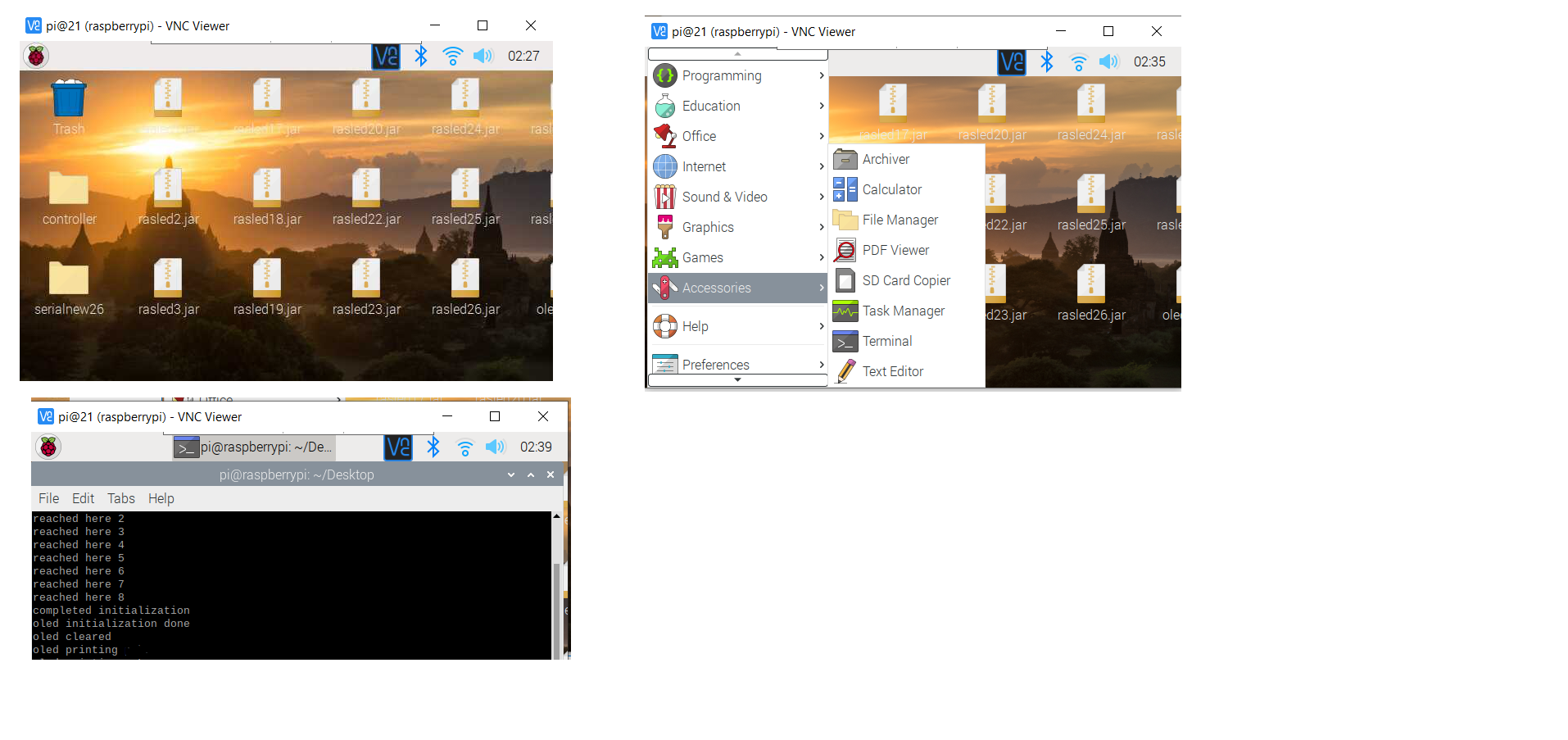
   You will see Raspberry Pi   screen on VNC
   Click on the Raspberry Pi   icon --->Accessories -->Terminal


    After it opens type

                      cd Desktop
                      ls
                      sudo java -jar oled102.jar


                     Note: Type the name of your jar file instead of oled102.jar
                                                  Press Enter

Bluetooth Tutorial for Oled using Arduino
  This is the tutorial for connecting bluetooth with oled using Arduino
  As most tutorials on youtube are just for switching the led on/off
  which are not that useful.

  There are 4 pins on bluetooth
  The connetions are as follows

  VCC  ----> VCC of arduino
  GND  ----> GND of arduino
  TX   ----> RX of arduino
  RX   ----> TX of arduino

  Its a prerequisite that you visit tutorials on oled
  Though This tutorial is for oled you can use it for LCD as well
  #include "U8glib.h"
U8GLIB_SSD1306_128X64 u8g(13,11,10,9,8);
int times,hours,mins,hoursf,minsf;

void setup(void)
{
Serial.begin(9600);
hours=6;
mins=15;
}

void loop(void)
{

if(Serial.available()>0)
  {
     times=Serial.read();
  }

 Switch(times)
 {
   Case 1:
   {
      if(hours>12)
        hours=0;
        else
         delay(500);
        hours=hours+1;
        u8g.firstPage();
      do{
              draw1();
           }while(u8g.nextPage());
}break;

Case 2:
{
if(mins>60)
mins=0;
else
delay(500);
mins=mins+5;
}break;


Case 3:
{
 if(mins<0)
mins=60;
else
delay(500);
mins=mins-5;
}break;

Case 4:
{
if(mins>60)
mins=0;
else
delay(500);
mins=mins+1;
}break;


Case 5:
{
if(mins<0)
mins=60;
else
delay(500);
mins=mins-1;
}break;


Case 6:
{
if(hours<0)
hours=12;
else
delay(500);
hours=hours-1;
}break;


Case 7:
{
hoursf=hours;
minsf=mins;
}break;


Serial.print(times);
delay(1000);

u8g.firstPage();
do{
   draw();
}while(u8g.nextPage());
delay(50);


}


void draw(void)
{

u8g.setFont(u8g_font_unifont);
u8g.drawStr(0,22,"blue");
u8g.drawStr(0,32,"tooth");
u8g.setPrintPos(107,20);
u8g.print(hours);
u8g.drawStr(72,35,"min");
u8g.setPrintPos(107,25);
u8g.print(mins);
u8g.drawStr(72,50,"hf");
u8g.setPrintPos(107,50);
u8g.print(hoursf);
u8g.drawStr(72,65,"mf");
u8g.setPrintPos(107,65);
u8g.print(minsf);


}


void draw1(void)
{
u8g.setFont(u8g_font_unifont);
u8g.drawStr(0,40,"connected");

}
Oled Clock Tutorial
 This is the tutorial on OLED Clock for this you require an OLED and arduino uno
 The Clock displays calendar and time as this is an analog clock
 we are going to use 3 hands hours,mins and seconds.
#include "U8glib.h"
int i,rs[30],rm[30],x[30],y[30],
p[30],q[30],a[50],b[50],rh[50];

int j,th1,th2,th3,k;
int hours,mins,seconds,sec_angle,min_angle,
hour_angle,times,hoursf,minsf;
int ha=hour_angle;
int ma=min_angle;
int sa=sec_angle;

float pi =3.1416;
int screenshift_x,screenshift_y;


U8GLIB_SSD1306_128x64 u8g(13,11,10,7,6);

void draw(void)
{

for(i=1;i<22;i++)
{
u8g.drawPixel(x[i],y[i]);
}


for(j=1;j<26;j++)
{
u8g.drawCircle(p[j],q[j]);
}


for(k=1;k<10;k++)
{
u8g.drawCircle(a[k],b[k]);
}

}


void setup(void)

{

hours=7;
mins=55;
seconds=0;

for(i=1;i<23;i++)
{
rs[i]=i;
}


for(j=1;j<26;j++)
{
rm[j]=j;
}


for(k=1;k<13;k++)
{
rh[k]=k;
}


}


void loop(void)
{

u8g.setFont(u8g_font,u8g_unifont)
hour_angle=hours*30;
mins_angle=mins*6;
sec_angle=seconds*6;

//picture loop

for(th3=ha-90;th3=ha+270;th3=th3+90)


{


for(th3=ma-90;th2=ma+270;th2=th2+6)


{

for(th1=sa-90;th1=sa+270;th1=th1+6)
{

for(i=1;i<23;i++)
{

x[i]=(rs[i]*cos(th1*pi/180))+64+32;

y[i]=(rs[i]*sin(th1*pi/180))+32;
}

for(j=1;j<26;j++)
{

p[j]=(rm[j]*cos(th1*pi/180))+64+32;

q[j]=(rm[j]*sin(th1*pi/180))+32;
}

for(k=1;k<13;j++)
{

a[k]=(rh[k]*cos(th1*pi/180))+64+32;


b[k]=(rh[k]*sin(th1*pi/180))+32;
}


delay(838);
u8g.firstPage();
do
{

draw();
u8g.drawStr(10,20,"THU");
u8g.drawStr(10,35,"21 JUL");

u8g.drawStr(10,50,"2016");
u8g.drawCircle(96,32,31);

u8g.drawCircle(110,7,1); //1

u8g.drawCircle(121,19,1); //2

u8g.drawCircle(121,46,1); //4


u8g.drawCircle(110,57,1); //5


u8g.drawCircle(82,57,1); //7
u8g.drawCircle(71,46,1); //8

u8g.drawCircle(71,19,1); //10

u8g.drawCircle(82,7,1); //11


u8g.drawStr(88,13,"12");

u8g.drawStr(93,62,"6");

u8g.drawStr(66,37,"9");

u8g.drawStr(119,37,"3");

}while(u8g.nextPage());
delay(5);
delay(100);

}

}

}


}
  The U8glib is the library we require ,the draw() function draws the hours,mins and
  secs hand of the respective length.

  The void setup is used to set the time we have choosen hours=7
  mins=55 and secs=0.


  The 3 for loops following it are just for drawing are for drawing the
  following hands.Now inside the main loop the hour_angle is defined as
  hours*30,it is 30 because the hour hand has to travel 5 degree and each degree
  is of 6 units.Similarly for mins_angle and secs_angle they have to travel
  just a degree which is of 6 units each.Hence mins*6 and secs*6.

  Now for drawing the analog clock The outermost loop is for hours and the innermost
  is for seconds hand.The code inside this loop is to set the timer at 12
  Inside the inner most for loop we are drawing all the 3 hands.

  We are giving a delay of 838 secs because while executing the loop lags a bit

  The code following it is for drawing the calendar and outlet of the
  Analog clock and the numbers on it.
UART Communication between Raspberrypi and Arduino
 This is a basic demonstration for  UART communication
 between  Raspberry Pi and  Arduino
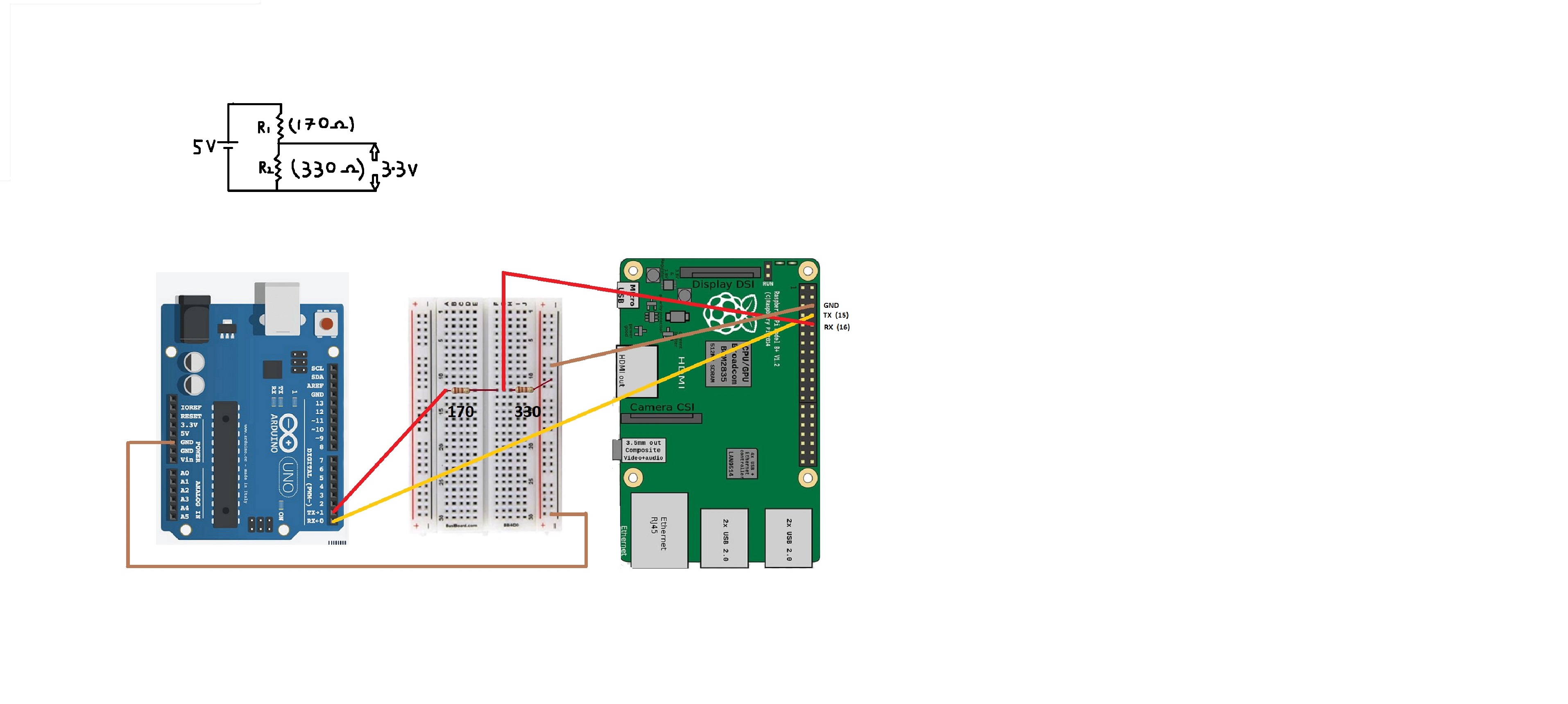
 The UART communication is simple but Arduino and Raspberry Pi works on different potential levels
 Arduino uno operates on 5V whereas Raspberry Pi operates on 3.3 V so when we are connecting
 Tx of Arduino to Rx of Raspberry Pi we have to use Potential divider
  The connections can be done as seen in the diagram shown below
  Tx of Raspberry Pi going to Rx of Arduino
  Tx of Arduino is going to R1 and the common point between R1 and R2 is going to Rx of Raspberry Pi
 For Programming I have used Arduino ide  for Arduino
 and Eclipse ide for RaspberryPi
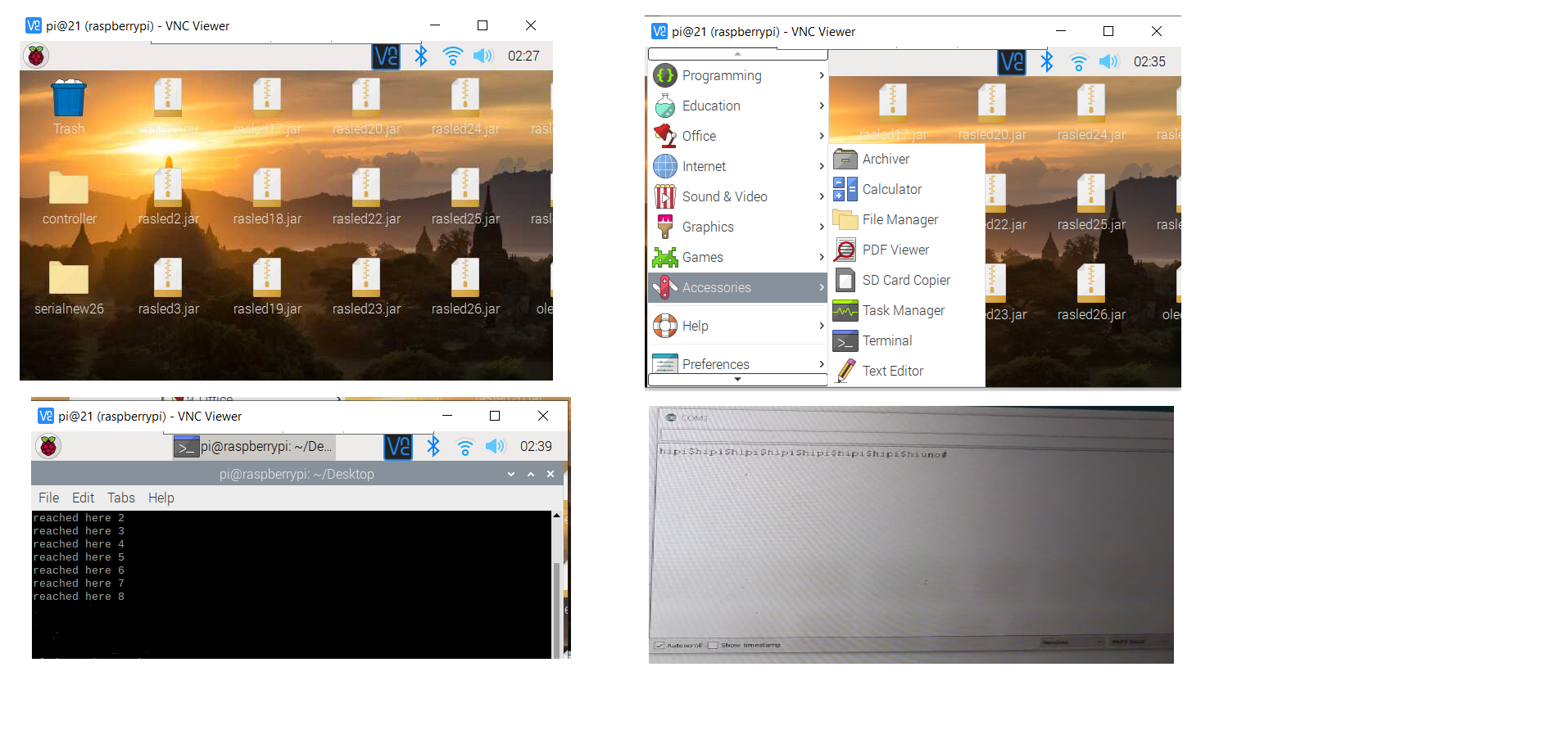
 In this Project Arduino transmits a string hipi$ continuously with a delay of 2 seconds..
 until the contactflag is 0 and simultaneously its checking if the stringComplete becomes true
 if the stringComplete becomes true it prints the String which is received from Raspberry Pi

 To receive data from Raspberry Pi I have used SerialEvent so whenever it will receives string
 ending with # it sets the stringComplete as true and sets contactflag to 1 which stops the transmission
 of hipi$


  Upload the code on Arduino and open Serial Monitor.
CODE FOR Arduino
int led=8;
int i=0;
int k=0;
String finaldata="";
String leddata="";
int contactflag;

String inputString = "";         // a String to hold incoming data
bool stringComplete = false;  // whether the string is complete

void setup() {
  Serial.begin(9600); // define baud rate
 pinMode(led, OUTPUT);
 digitalWrite(led, HIGH);
 contactflag=0;


}

void loop() {


          if(contactflag==0)
          {

             Serial.write("hipi$");
             delay(2000);
             //contactflag=1;
          }


         if (stringComplete)
         {


            Serial.println("the msg from pi is");
            Serial.println(inputString);


             inputString = "";


            stringComplete = false;
          }


}


void serialEvent() {
  while (Serial.available()) {
    // get the new byte:
    char inChar = (char)Serial.read();
    // add it to the inputString:
    inputString += inChar;

    if (inChar == '#') {

      stringComplete = true;
       contactflag=1;

    }
  }
}
  Its a prerequisite that you visit tutorials to
  Install   openjdk11 on your raspberry pi..the same jdk version should be on your laptop
  You can refer the link given below
  install openjdk11


  Download the following softwares on your laptop
   WinSCP (for transferring files from laptop to raspi)
   RealVNC (for virtually connecting laptop and raspi)


    The pin connection is based on wiring4j
  Please visit pi4j website for downloading the libraries and pin description

 Download the pi4j Library for the same with the help of the link given below


 pi4j library


  Open Eclipse ide on laptop

  File --> New --> Java Project-->In Project name --> Raspi -->Finish

  Open the Project

  src --> New -->Package -->controller1-->Finish

  controller1--> New --> Class --> serialnew -->Finish

  Refer the code given below and use that in your   class


  Scroll to the serialnew.java -->Right click--> Run as-->Java Application

  The console will show error ignore it for now as we are going to transfer our file to Raspberry Pi

  Right Click on the Raspi Project-->Export -->Java--> Runnable JAR file -->Next

  Launch configuration -->   serialnew -Raspi

  Export designation --> C:\User...\serialnew.jar

 I have also used their  SerialExample and modified it to use their code

 This is a link for the reference of their code
 Serial Example

 Serial and console object has been created and initialized accordingly
 In a continuously running while loop  actionListener has been called on serial object
 which triggers an  event and calls  dataReceived method if the received data
 is hipi$ and contactflag is 0 it transmits  hiuno# and
 sets the contact flag to 1
CODE FOR RaspberryPi
package controller;


import com.pi4j.io.serial.*;
import com.pi4j.util.CommandArgumentParser;
import com.pi4j.util.Console;

import java.io.IOException;
import java.util.Date;


public class serialnew


{

	static int flag=0;
	static int contactflag=0;
	 public static void main(String args[]) throws InterruptedException, IOException


	 {


		 System.out.println("hello uart 4");
		 final Serial serial = SerialFactory.createInstance();
		 SerialConfig config = new SerialConfig();
	        // create and register the serial data listener


	        try {
	            // create serial config object


	            config.device("/dev/ttyS0")
	                  .baud(Baud._9600)
	                  .dataBits(DataBits._8)
	                  .parity(Parity.NONE)
	                  .stopBits(StopBits._1)
	                  .flowControl(FlowControl.NONE);

	            // parse optional command argument options to override the default serial settings.
	            if(args.length > 0){
	                config = CommandArgumentParser.getSerialConfig(config, args);
	            }


	            serial.open(config);


	            while(true)
	            {

	            	 //System.out.println("reached here 0");

	            	 serial.addListener(new SerialDataEventListener() {
	     	            @Override
	     	            public void dataReceived(SerialDataEvent event) {
	     	            	 System.out.println("reached here 1");
	     	                // NOTE! - It is extremely important to read the data received from the
	     	                // serial port.  If it does not get read from the receive buffer, the
	     	                // buffer will continue to grow and consume memory.

	     	                // print out the data received to the console
	     	                try {

	     	                	System.out.println("reached here 2");
    	                    //System.out.println("[HEX DATA]   " + event.getHexByteString());
	     	                   // System.out.println("[ASCII DATA] " + event.getAsciiString());


	     	                   String   receiveddata1= event.getAsciiString();
	     	                  System.out.println(" data is" + receiveddata1 );


	    	                   //serial.write("$SecondLine#\r\n");

	     	                  if(receiveddata1.contains("hipi$")&&(contactflag==0))
	     	                  {
	     	                	 System.out.println("data received");
	     	                	 contactflag=1;
	     	                	  serial.write("hiuno#");
	     	                	  System.out.println("data transmitted");


	     	                  }


	     	                } catch (IOException e) {
	     	                    e.printStackTrace();
	     	                }
	     	            }
	     	        });


	            }

	        }
	        catch(IOException ex) {
	            System.out.println(" ==>> SERIAL SETUP FAILED : " + ex.getMessage());
	            return;
	        }


	 }

}
  Open the    WinSCP software
  login Screen will appear

  Host Name : 192.168.0.21  WinSCP  (your assigned ip address)
  User Name :   pi (your assigned username) Password:  123456  (your assigned password)
  Drag the file from laptop to Raspberry Pi

  Open the   RealVNC Software


  File -->New Connection
  VNC Server : 192.168.0.21  192.168.0.21  (ip address of pi)
  Name :   pi@21 click OK

  A new window will appear click on the icon pi@21
  Username:     Pi  (your assigned username for pi)
  Password :  123456 (your assigned password for pi)

   You will see Raspberry Pi   screen on VNC
   Click on the Raspberry Pi   icon --->Accessories -->Terminal


  If the serial port is transmitting   random data to arduino
  open the  terminal of Raspberry Pi type
   sudo raspi-config Press Enter
   A pop up screen will appear

   Select Interfacing option

   Select Serial
  A question will pop up : Would you like a login shell to be
                                      accessible over serial?
  Select  No

 After that go back to the termial window


                      cd Desktop
                      ls
                      sudo java -jar serialnew.jar


                     Note: Type the name of your jar file instead of serialnew.jar
                                                  Press Enter
Weighing scale using Arduino
#includeLiquidCrystal lcd(12, 11, 5, 4, 3, 2); const int clk=2; const int adc_data_pin=3; const int key1=8; const int key2=9; unsigned int a,b,c,d,i,j,knownwt,sh,ch,mode; unsigned long adc_val=0.00; float adc_avg=0.00,tares=0.00,conv; float b_adc,b_adc_kg,b_adc_pound,adc_act; String mystring,msg1,msg2,msg3,msg5,msg6,msg7,msg8,msg9,msg10; void setup() { pinMode(key1,INPUT); pinMode(key2,INPUT); pinMode(clk,OUTPUT); pinMode(adc_data_pin,INPUT_PULLUP); Serial.begin(9600); lcd.begin(16,2); msg1=String("CALIBRATION"); msg2=String("loadcell"); msg3=String("TARE"); msg5=String("PLACE wt"); msg6=String("REMOVE wt"); msg7=String("g"); msg8=String("kg"); msg9=String("lbs"); msg10=String("tola"); } void loop() { int key1state = digitalRead(key1); int key2state = digitalRead(key2); lcd.setCursor(1,2); lcd.print(msg2); while(1) { adc_act=52428; adc_read(); mode=1; switch(mode) { case 1: { b_adc=(knownwt*(adc_avg-tares))/(adc_act); lcd.setCursor(1,4); lcd.print(msg7); mystring=String(b_adc); lcd.setCursor(2,4); lcd.print(mystring); }break; case 2: { b_adc=(knownwt*(adc_avg-tares))/(adc_act); b_adc_kg=(b_adc/1000); lcd.setCursor(1,4); lcd.print(msg8); mystring=String(b_adc_kg,2.00); lcd.setCursor(2,4); lcd.print(mystring); }break; case 3: { b_adc=(knownwt*(adc_avg-tares))/(adc_act); b_adc_pound=(b_adc/454); lcd.setCursor(1,4); lcd.print(msg9); mystring=String(b_adc_pound,2.00); lcd.setCursor(2,4); lcd.print(mystring); }break; default: { } } key (); } } void adc_read() { int i,j,read_no; unsigned long adc_val; data_read=digitalRead(adc_data_pin); digitalWrite(clk,0); while(data_read==1); read_no=0; adc_val=0; digitalWrite(clk,1); adc_val=adc_val<<1; digitalWrite(clk,0); if(data_read) { adc_val++; read_no++; if(read_no>=26) { digitalWrite(clk,1); adc_avg=(double)adc_val; digitalWrite(clk,0); } } } void tare(double tares) { tares=0.00; tares=adc_avg; } void conversion(double conv) { sh=1; switch(sh) { case 1: { delay(200); mode=1; if(key1state==0) sh=2; } break; case 2: { delay(200); mode=2; if(key1state==0) sh=3; } break; case 3: { delay(200); mode=3; if(key1state==0) sh=1; } break; default: { } } } void calibration(unsigned int knownwt) { getnumber(); knownwt =(a*1000+b*100+c*10+d); mystring=String(knownwt); lcd.setCursor(2,1); lcd.print(mystring); } void key() { if(key1state==0) { lcd.setCursor(1,1); lcd.print(msg3); conversion (conv); } if(key2state==0) { lcd.setCursor(1,1); lcd.print(msg2); tare (tares); } if((key1state==0)&&(key2state==0)) { lcd.setCursor(1,1); lcd.print(msg1); calibration (knownwt); } } void getnumber() { ch=1; switch (ch) { case 1: { i=0; while(key2state==0 && i<=9) { i++; mystring=String(i); lcd.setCursor(2,1); lcd.print(mystring); } a=i; ch=2; } break; case 2: { delay(500); i=0; while(key2state==0) { i++; delay(200); mystring=String(i); lcd.setCursor(2,2); lcd.print(mystring); if(i>=10) i=0; } b=i; ch=3; } break; case 3: { delay(500); i=0; while(key2state==0) { i++; delay(200); mystring=String(i); lcd.setCursor(2,3); lcd.print(mystring); } c=i; ch=4; } break; case 4: { delay(500); i=0; while(key2state==0 && i<=9) { i++; delay(200); mystring=String(i); lcd.setCursor(2,4); lcd.print(mystring); } d=i; } break; default: { } } }
  This video demonstrates how to measure weights from 50 g to 10 Kg
  using 20 bit ADC HX710 and the result is displayed using LCD
Rubik's cube Solver Code
     The code written in java solves the Rubik's cube using   Blind cubing
     method.
     Its a prerequisite that you get information on how to solve a cube using blind cubing
     For Brief in blind cubing method the  corners are solved first followed by
      edges


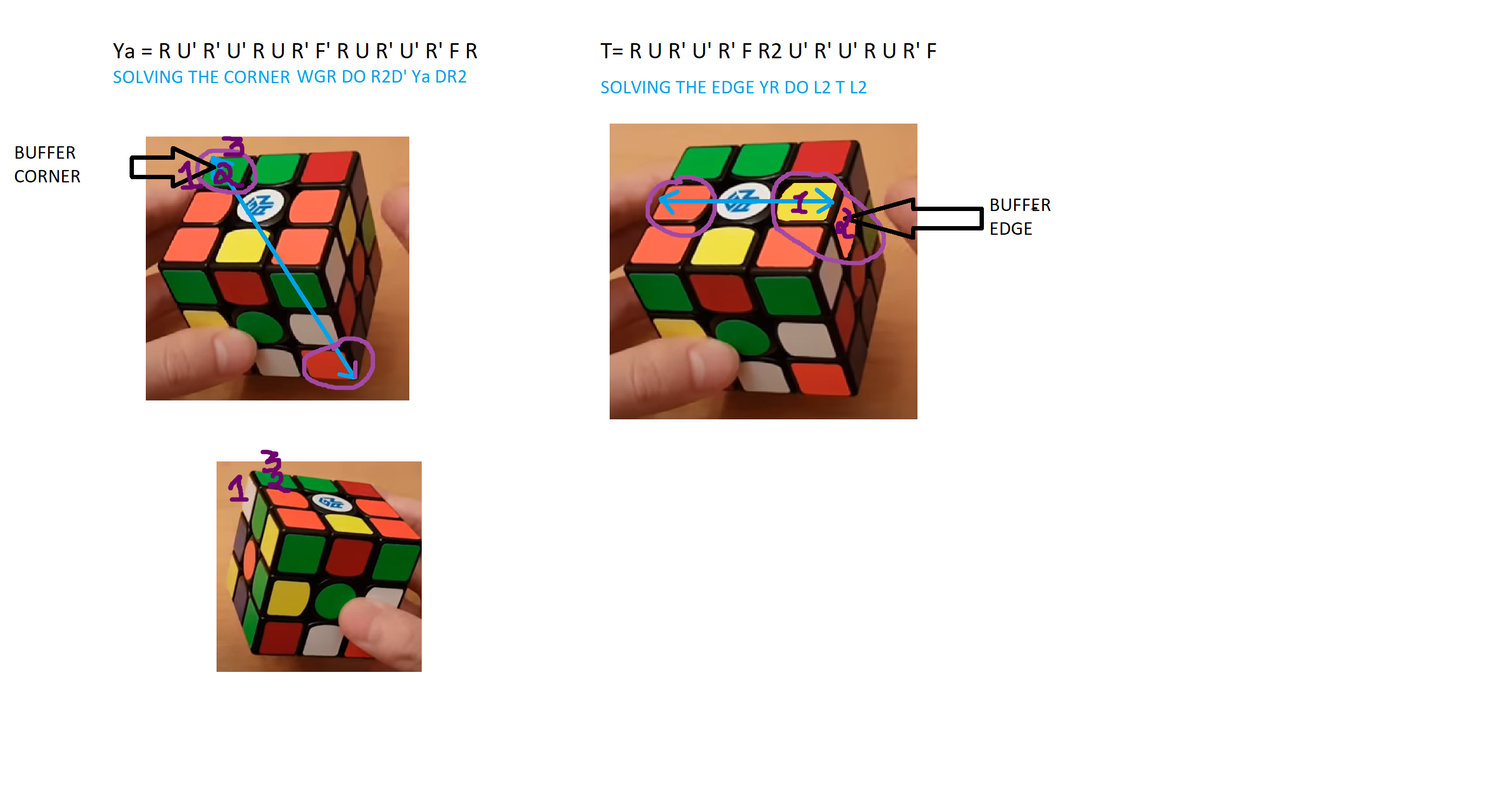
  	 Only  two algorithms are required to solve the cube Ya for the corners and T for the edges

     For solving the cube the green center faces the front and white center faces the top
     The cube is never rotated

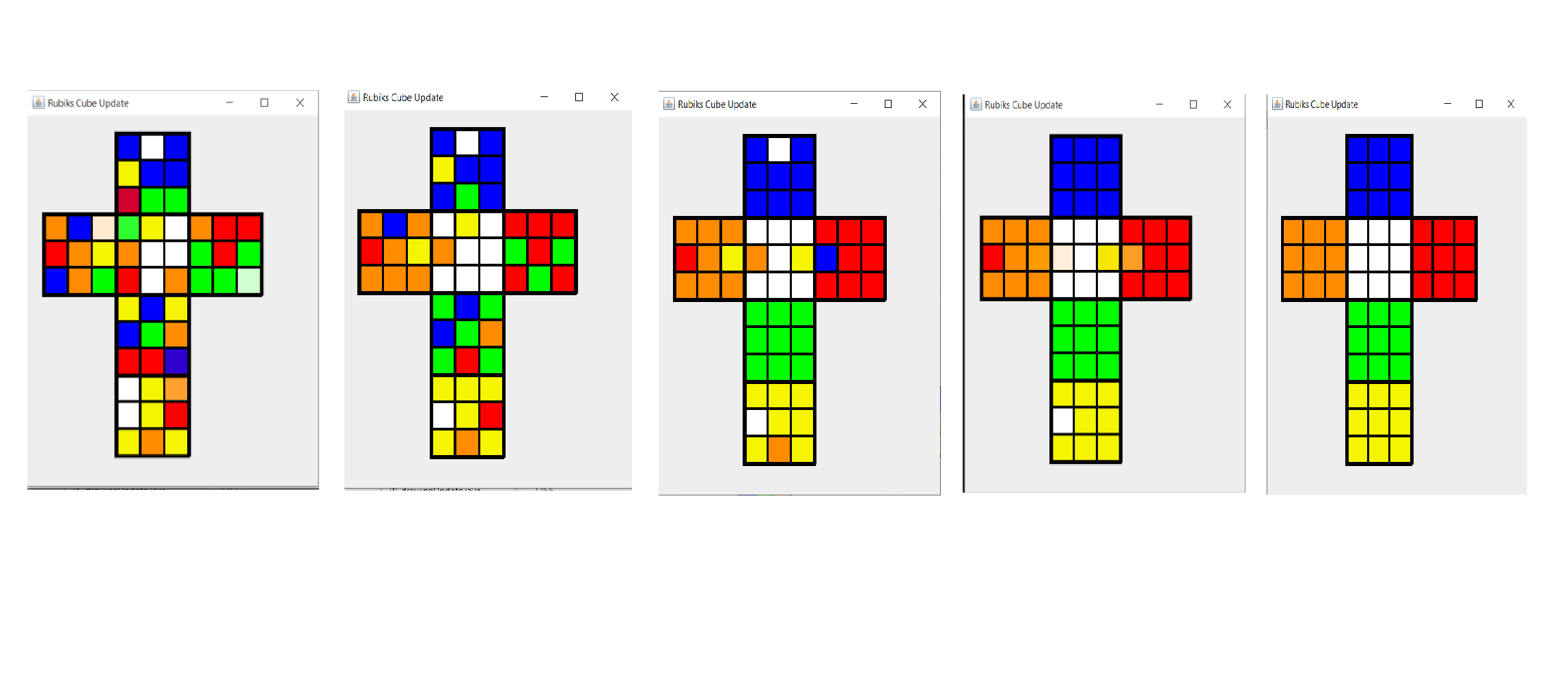
     Starting with solving the corners first..the corner  White-Green-Red (WGR) in its buffer
     location of corner as seen in the diagram is solved to its correct  position as well
     as   orientation doing   F2R' Ya RF2


     Similarly all the corners are solved

     Starting with the edges first .. the corner   Yellow-Orange (YO) in its buffer location
     of edge as seen in the diagram is solved to its correct  position as well as
      orientation doing  L2 T L2


      Similarly all the edges are solved which finally solves the cube
    Click on the link given below to access code on github

     github


    After downloading open the src folder you will find package named model
    Inside model you need two classes for this project

    Cube.java and drawingUpdate.java
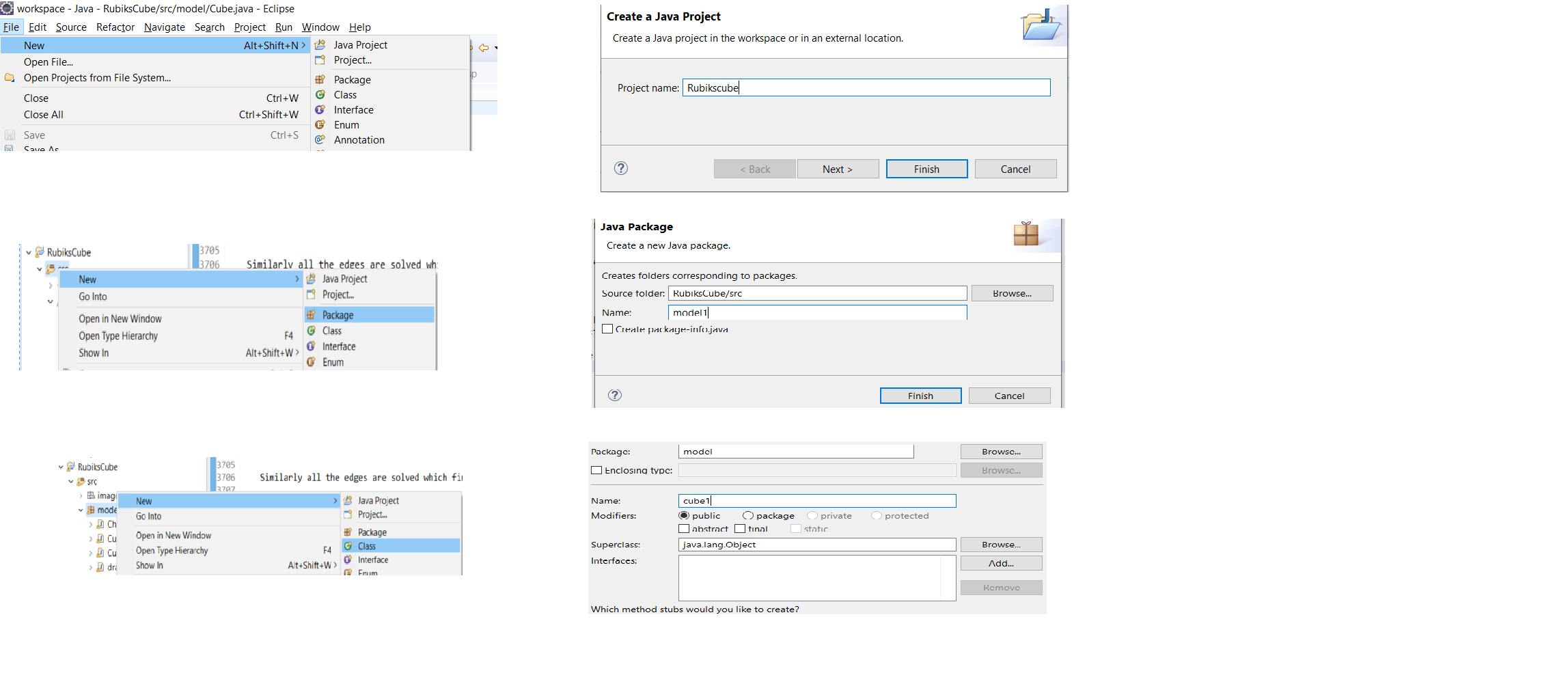
    For the project -->Open Eclipse ide

    File-->New--> Java Project

    Project Name:  RubiksCube -->Finish

    Open the project inside  src folder-->New -->Package
    Name :  model


    Create two classes namely  Cube and  drawingUpdate


    Open the model -->New-->Class
    Name :  Cube

    Open the model -->New-->Class
    Name :  drawingUpdate
     Now proceeding with the code


     Cube.java is  the class that contains the  main class
      swing Technology of java is used for 2D graphics
     All the 6 faces are divided into  3x3 matrix and initialized

       data7 =  Cube.CheckPosCor();

      Stores the String of the corner located in the buffer location
      after that inside a while loop a method  Cube.getPosCor(data7)
      is called until all the   cornersare solved


      In   getPosCor() a matrix   rubcor is updated..which is further used
      in a while loop where   data13=CheckCor()  is called
      for displaying the moves to solve all the corners

      Similarly

       data9 =  Cube.CheckPosEd()
       Stores the String of the edge located in the buffer location
       after that inside a while loop a method Cube.getPosEd(data9)
       is called until all the edges are solved

       In  getPosEdgetPosEd a matrix rubed is updated...which is further used
       in a while loop where  data14=CheckEd() is called
       for displaying the moves to solve all the edges


       Cube.displayUpdate()  is used for graphics

       Which ultimately  solves the cube
Rubik's cube solver using ARM
  This video shows a bot and it solves any given scramble in less
  than 1 min 30 secs using  CFOP method.We have used ARM micro
  controller for this which instructs 6 stepper motors according
  to the moves generated in the algorithm to solve the cube
LED Rubik's cube theme decoration
  In this project we  made a LED Rubik's cube which depicts actual moves in the cube.
  It scrambles itself,resolves itself and also shows 20 different patterns that can be done
  on actual  Rubik's  cube.

  Its not only mesmerizing but also easy to make

  To make this project simple..lets divide it into 3 parts

   Electronics  Part:


  For our project we have used   Arduino Mega
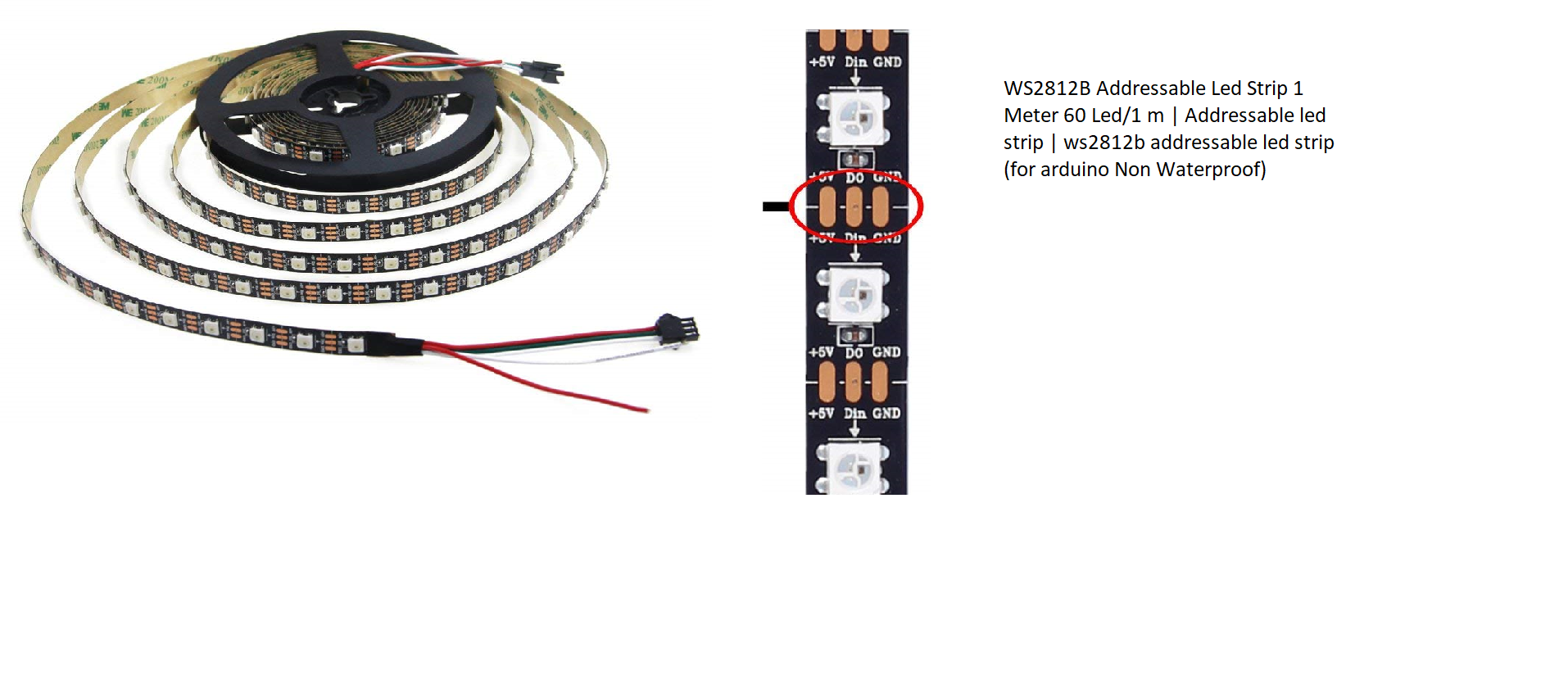
  WS2812B Addressable Led Strip 1 Meter 60 Led/1 m
  We need a total of 486 led's so we have used
  approximately 8.5 m strip
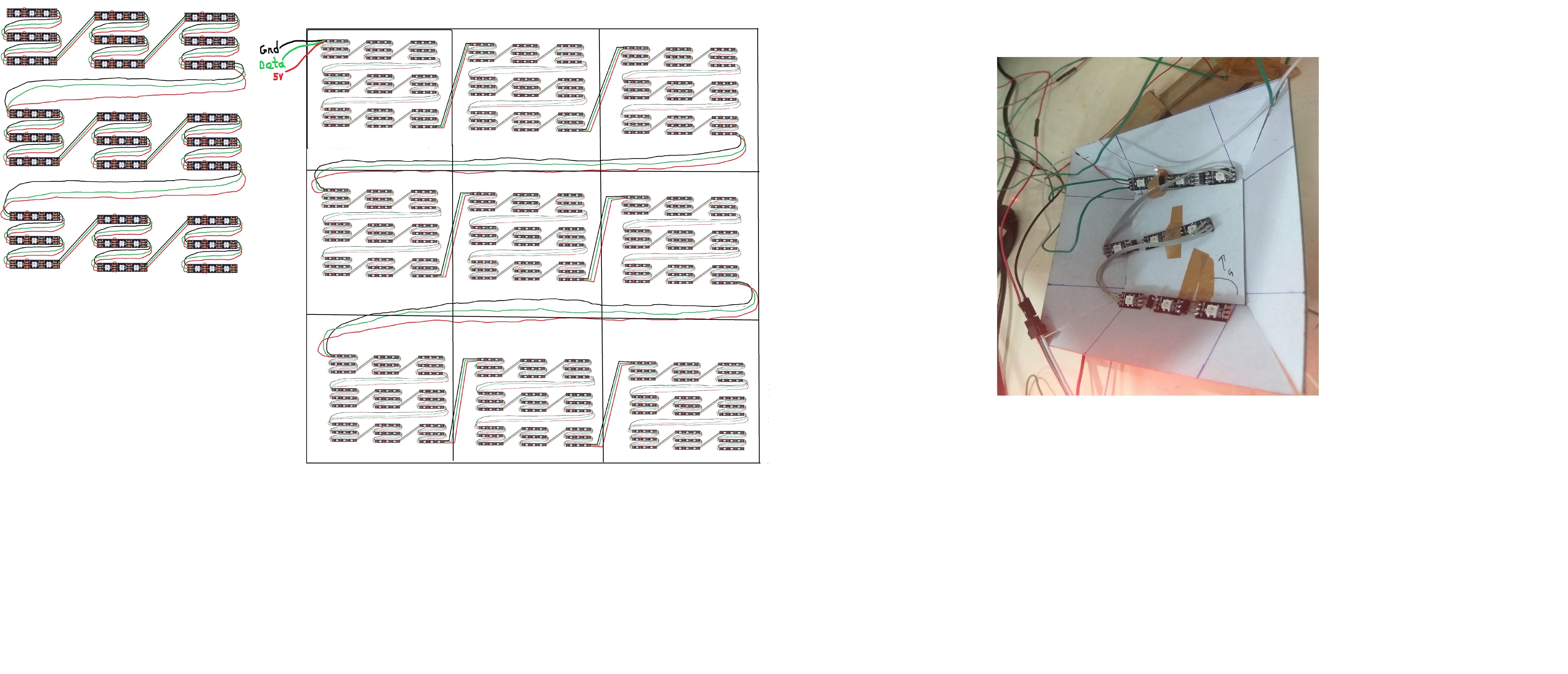
  As you can see in the diagram for one side of a cube we have 9 squares
  consisting of 1 center 4 edge pieces and 4 corners
  Each square piece has 9 led's so total led's required on single side
  are 81 led's
  If you closely look at the ledstrip it has 3 inputs 5v,gnd and a
  data, The connections are done as seen in the diagram for a single side


  You have to repeat this for all 6  sides.
  After all the connections are done you will have a  5V  wire,
  a  gnd  wire and a  data  wire attached to the first led of all sides
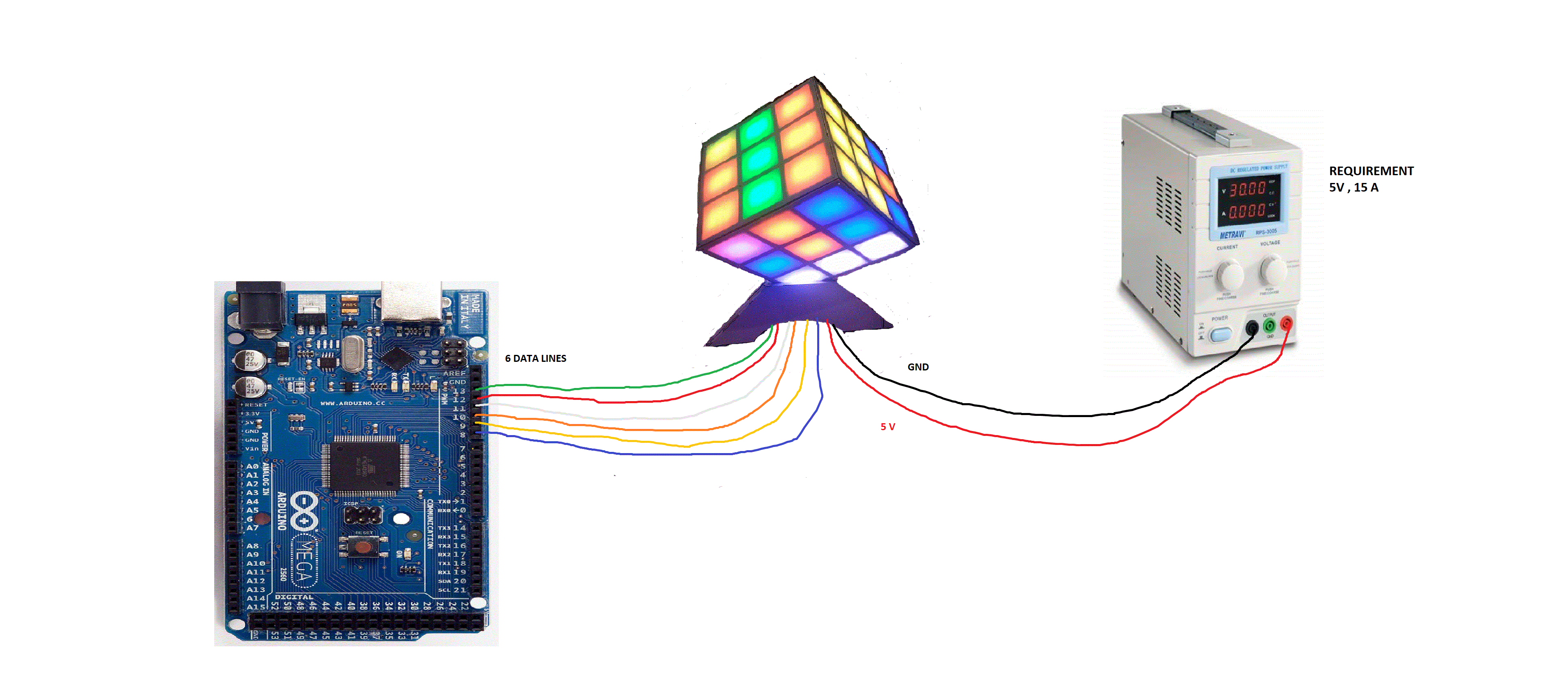
  All the 6 wires of 5v should be shorted similarly the 6 wires of
  gnd should be shorted and attached to the  power supply

  Note:That though voltage required is 5V because of 486  led's the
  total current required is approximately 15 A .

  The 6 data lines  individually goes to the  6 ports of
  Arduino mega as shown in the diagram.
    Mechanical Part:

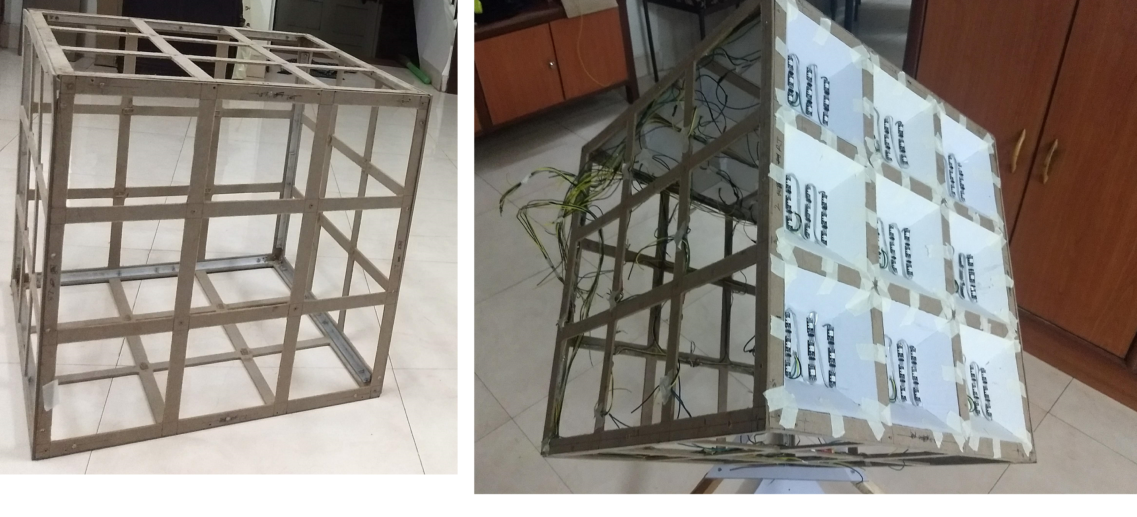
  We made a squared aluminium frame
  Then for making a side of a cube we took 6 wooden
  frames and for all the frames we took out  9 sqaure
  portions and also made a cube stand  as seen in the diagram
  For placing 9 led's we made a tray shaped box of
  cardboard and sticked the led strip with paper tape

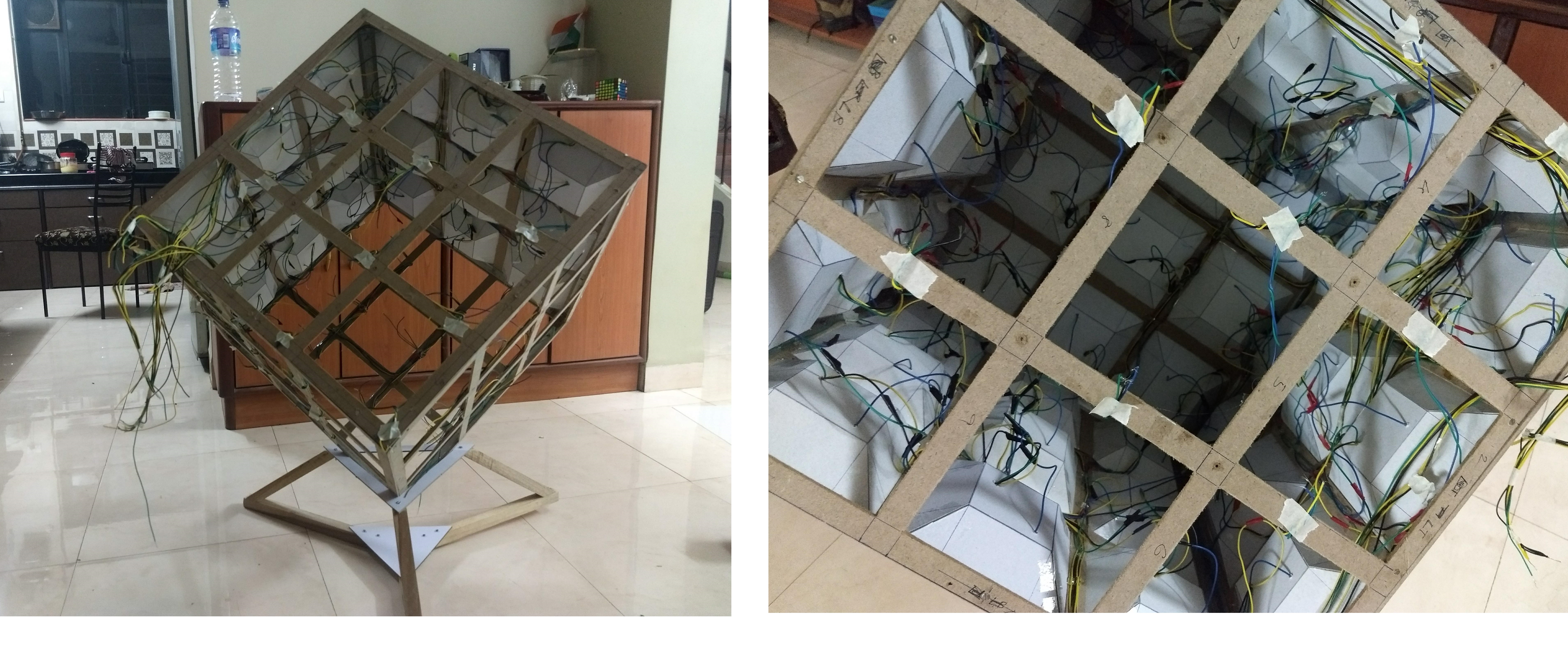
  After all  81 led's were placed in 9 tray boxes we
  attached it to the wooden frame as shown in the diagram
  We took 6  acrylic sheets of the length of the wooden frame
  and covered the entire cube.
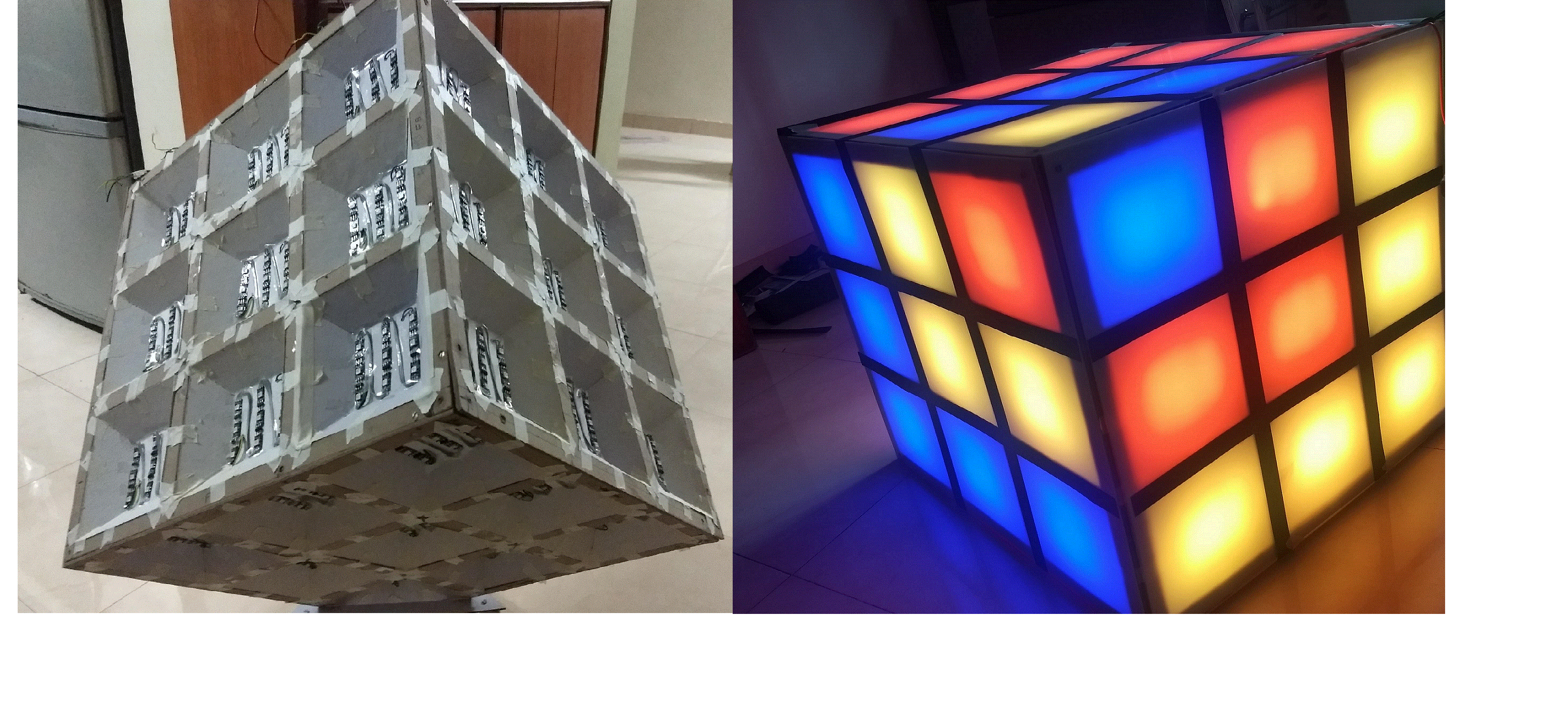
  Then attached black craft paper to cover the entire cube
  so that it   mimics
  the visualization of actual Rubik's cube
    Coding Part:

   Code Credits:   Sahil Dalvi & Shamika Dalvi

  Click on the link given below to access code on

     github


  After making electrical connections and making mechanical
  assembly the most important part was to bring the cube to  live
  so tha it mimics the Rubik's cube

  We have used arduino mega and used   FastLed   library

   Visit this link for basic examples


    github example


  We have defined a    CRGB
  leds[6][81] which can takes a rgb color
  The 6 signifies the side and 81 the total number of led's
  on a side


  leds[0] corresponds to  blue side
  leds[1] corresponds to  yellow side
  leds[2] corresponds to  orange side
  leds[3] corresponds to  white side
  leds[4] corresponds to  red side
  leds[5] corresponds to  green side


  side[6][81] is used for updating the leds[6][81] matrix.

  initializePos() function is to  initialize cube matrix

  displayLed() function is to display the led's

   Inside 2 for loops consisting of side and color
   The value of the side matrix is stored in a r1 variable

   and according to the value it corresponds from 0 to 5
   leds matrix is updated 0 corresponds to blue color
   and  5 corresponds to green color


   In the void loop 5 patterns are displayed
   and then a MoveSide(char number) function is called
   which does any random moves and stores that in a
   array.


   If inside a MoveSide(char number) function if case 0 is
   executed it stores that R move is done and calls moveR() function.


   moveR() function actually depicts the Right move done
   on a rubik's cube.


   Similarly the moveU() function depicts the Up move
   done on a rubiks's cube.


   Similarly all the moves that are done on a Rubik's cube
   can be done on LED Rubik's cube
Fibonacci Flower
     In the video as it can be seen the  fibonacci flower creates an  illusion
     of blooming,being still, blooming inwards sometimes rotating clockwise sometimes
     rotating anti clockwise or showing different patterns

     This is achieved by an effect known as the stroboscopic  effect which
     is a  phenomenon due to interrupted illumination of a moving object

     Fibonacci Flower as the name suggest is a mathematical flower based on fibonacci
     series designed by JOHN EDMARK
     the corresponding golden angle for that is 137.5
     degree so that all the petals are equally spaced


      JOHN EDMARK WEBSITE


      To make this project simple we have divided it in 3 parts
     Electronics Part:

     To achieve the  stroboscopic effect the frequency
     of the LED's are controlled with the help of using  Arduino.


     The LED's required for this project are of  12V,20 W
     and arduino can't drive them hence we have to use a mosfet

     As you can see in the diagram we have used a Mosfet IRF540 N as mosfet has high input
     capacitance we have to use mosfet driver IR2101
     which drives the mosfet.

     The connections can be seen in the diagram.The Intel CPU fan has 3 wires

     It has inbuilt  sensor which gives two
     pulsesafter the fan completes a single rotation


     The red wire which is the Vcc is connected to 12V.
     The black wire is connected to ground wire
     The green wire is has to be pulled up to 5v and its connected to pin no 2 of Arduino.


     The pin no 8 of Arduino is attached to the pin no 3 of Mosfet driver
     and the Arduino triggers the mosfet driver according to the code which is explained later


     Pin no 5 of mosfet driver is to the gate of mosfet
     The source of the mosfet is connected to ground


     2 LED's are connected in series one end of the LED is connected to 24V along with a resistor
     The other end is connected to the drain of the mosfet.


     Note: In our project the wire connecting the drain and Led as well as the resistor
     and led are extended so that the LED's can be attached at the top of the structure.
        Mechanical Part:

     In our project  the fibonacci flower is attached to the intel CPU fan which rotates at a RPM of 1200

    Two acrylic sheets have been arranged to form a   rectangular shape.
    The CPU fan is attached to the bottom and   beneath that the electronic
    circuit is placed.Two LED's attached with the wired are sticked to one acralic sheet and placed on the top of rectangular shape.

volatile boolean state = 0;
volatile int counter = 0;
volatile int state_counter = 0;
int mode = 0;
float Dc = 0.25;  //duty cycle in %

unsigned long PuleTimeMonitor_start = 0;
unsigned long PuleTimeMonitor_mode_start = 0;
unsigned long PuleTimeMonitor_end = 0;
unsigned long PuleTimeMonitor_mode_end = 0;
unsigned long timeDiff_us= 0;

unsigned long  TpulseTot_us = 0;
unsigned long timecntoffset = 0;

unsigned long Ton_us = 100;
unsigned long Toff_us = 10000;
unsigned long Tchangemode = 5000000;  // 5seconds
unsigned long Ttrigger = 0;

int pulses ; // no of pulses
int pulseCounter;
float AngleRemaining; // remaining angle to complete the circle
float AngleReq = 222.52;   // required angle in gedtrees
float Angleoffset = 0;  // offset angle in degrees
float AngleActual;
float AnglePulseMain;
float AnglePulseOffset;


void setup()
{
  Serial.begin(38400);
  pinMode(8,OUTPUT);
  pinMode(13,OUTPUT);
  pinMode(2,INPUT);
  attachInterrupt(digitalPinToInterrupt(2),buttonPressed, RISING);

   pulses = 360 / AngleReq;
}

void loop()
{
  if(state == true)
  {
      state = false;
      if(mode == 8)
      {
        LEDtoggle_static();
      }
      else
      {
        if(counter == 0)
        {
          PuleTimeMonitor_start = micros(); //  millis();
          PuleTimeMonitor_mode_start = micros();
        }

        if(counter == 1)
        {
          PuleTimeMonitor_end = micros(); // millis();
          timeDiff_us = PuleTimeMonitor_end - PuleTimeMonitor_start;
          PuleTimeMonitor_start = PuleTimeMonitor_end;

          pulses = 360 / AngleReq;
          for(pulseCounter = 0; pulseCounter <= pulses; pulseCounter++)
          {
              AngleActual = (pulseCounter*AngleReq) + Angleoffset;
              AngleRemaining = 360 - AngleActual;
              AnglePulseMain = AngleActual/360;
              if(AngleRemaining <= AngleReq)
              {
                Angleoffset = AngleReq  - AngleRemaining;
                pulseCounter = pulses + 1;
              }
              Ttrigger = timeDiff_us * AnglePulseMain ;
              TpulseTot_us = timeDiff_us; //     /pulses;
              Ton_us = (Dc*TpulseTot_us)/100;

              while((micros() - PuleTimeMonitor_end) < Ttrigger);
              LEDtoggle();


            }
          }
        counter = 1;
      }
  }
}

void buttonPressed()
{
  /******Fan Pulse Monitor****************/
  if(state_counter == 0)
  {
    state = false;
    state_counter =1;
  }
  else if(state_counter == 1)
  {
    state = true;
    state_counter = 0;
  }
 // state_counter = state_counter + 1;


  /******Fan Pulse Monitor end****************/

/******Mode Selector***************/

  if((micros() - PuleTimeMonitor_mode_start) > Tchangemode)
  {
    Serial.print(" mode = ");
    Serial.println(mode);

    PuleTimeMonitor_mode_start = micros();
    if(mode == 0)   // blooming
    {
      AngleReq = 137.5;

      mode =1;
    }

    else if(mode == 1)
    {
      AngleReq = 222.5;

      mode =2;
    }

    else if(mode == 2)
    {

      AngleReq = 309;
      mode = 3;
    }

    else if(mode == 3)
    {

      AngleReq = 306;
      mode = 4;
    }

    else if(mode == 4)
    {

      Angleoffset = 0;
      counter = 0;
      mode = 5;
    }

    else if(mode == 5)
    {

      AngleReq = 189.25;
      mode = 6;
    }

    else if(mode == 6)
    {

      AngleReq = 359;
      mode = 7;
    }


    else if(mode == 7) //
    {

      AngleReq = 361;
      mode = 8;

    }

    else if(mode == 8) // static
    {

      AngleReq = 277.5;
      mode = 0;
    }


  }

  /******Mode selector end ****************/
}

void dispData()
{
    Serial.print(" Angle = ");
    Serial.println(AngleActual);

}

void LEDtoggle()
{

   digitalWrite(8, HIGH);
   delayMicroseconds(Ton_us);
   digitalWrite(8, LOW);


}

void LEDtoggle_static()
{

   digitalWrite(8, HIGH);
   delayMicroseconds(150);
   digitalWrite(8, LOW);


}

void LEDtoggle_speed()
{

   digitalWrite(8, HIGH);
   delayMicroseconds(100);
   digitalWrite(8, LOW);
   delay(1);


}
       Code Credits :  Sahil Dalvi

      In the code various parameters have been initialised
      The duty cycle has been set to  0.5% ,
      Pin no 8 of arduino is set as output and pin no 2 is set to receive input which triggers
       interruptand calls buttonPressed() function and 8 modes are set.
      In  void loop() function it the mode 8 is not achieved then and if the counter is 1
      timedifference,pulses,angleactual,angleremianing and angleoffset are calculated

      According to the number of pulses a for loop is executed  the Ton is calculated
      and  LEDtoggle() function is called to trigger the mosfet driver which triggers
      the LED
TFT 3.5" Calculator display
 This is a tutorial for calculator using Arduino TFT 3.5" display
 This is coded for performing 4 basic arithmetic operations
#include#include #include MCUFRIEND_kbv tft; MCUFRIEND_kbv tft; #define YP A3 // must be an analog pin. #define XM A2 // must be an analog pin. #define YM 9 // can be a digital pin. #define XP 8 // can be a digital pin. #define TS_MINX 116 #define TS_MINY 955 #define TS_MAXX 893 #define TS_MAXY 102 #define BOXSIZE 40 #define PENRADIUS 3 int oldcolor, currentcolor; // For better pressure precision, we need to know the resistance // between X+ and X- Use any multimeter to read it // Its about 300 ohms across the X plate on mine. TouchScreen ts = TouchScreen(XP, YP, XM, YM, 300); // Assign human-readable names to some common 16-bit color values: #define BLACK 0xFFFF #define BLUE 0xFFE0 #define GREEN 0xF81F #define CYAN 0xF800 #define GRAY1 0x8410 #define RED 0x07FF #define GRAY2 0x4208 #define MAGENTA 0x07E0 #define YELLOW 0x001F #define WHITE 0x0000 #define PINK 0x07E0 #define MINPRESSURE 5 #define MAXPRESSURE 1500 /* String symbol[4][4] = { { "7", "8", "9", "/" }, { "4", "5", "6", "*" }, { "1", "2", "3", "-" }, { "C", "0", "=", "+" } }; */ String symbol[4][4] = { { "/", "*", "-", "+" }, { "9", "6", "3", "=" }, { "8", "5", "2", "0" }, { "7", "4", "1", "C" } }; int X,Y; long Num1,Num2,Number; char action; boolean result = false; void setup(void) { Serial.begin(9600); Serial.println(F("Paint!")); tft.reset(); uint16_t identifier = tft.readID(); Serial.print(F("LCD driver chip: ")); Serial.println(identifier,HEX); tft.begin(0x9486); tft.fillScreen(WHITE); tft.setRotation(2); Screen(); drawButtons(); } void loop() { pinMode(XM, OUTPUT); pinMode(YP, OUTPUT); Point p; do { p = ts.getPoint(); pinMode(XM, OUTPUT); pinMode(YP, OUTPUT); } while((p.z < MINPRESSURE )|| (p.z > MAXPRESSURE)); p.x = map(p.x, TS_MINX, TS_MAXX, 0, 320); p.y = map(p.y, TS_MINY, TS_MAXY, 0, 480); Y = p.x; X = p.y; DetectButtons(); if (result==true) CalculateResult(); DisplayResult(); delay(300); } void DetectButtons() { if (X<80 && X>0) //Detecting Buttons on Column 1 { if (Y>0 && Y<85) //If cancel Button is pressed { Serial.println ("Cancel Button"); Number=Num1=Num2=0; result=false;} if (Y>85 && Y<160) //If Button 1 is pressed {Serial.println ("Button 1"); if (Number==0) Number=1; else Number = (Number*10) + 1; //Pressed twice } if (Y>160 && Y<240) //If Button 4 is pressed {Serial.println ("Button 4"); if (Number==0) Number=4; else Number = (Number*10) + 4; //Pressed twice } if (Y>240 && Y<320) //If Button 7 is pressed {Serial.println ("Button 7"); if (Number==0) Number=7; else Number = (Number*10) + 7; //Pressed twice } } if (X<160 && X>80) //Detecting Buttons on Column 2 { if (Y>0 && Y<85) {Serial.println ("Button 0"); //Button 0 is Pressed if (Number==0) Number=0; else Number = (Number*10) + 0; //Pressed twice } if (Y>85 && Y<160) {Serial.println ("Button 2"); if (Number==0) Number=2; else Number = (Number*10) + 2; //Pressed twice } if (Y>160 && Y<240) {Serial.println ("Button 5"); if (Number==0) Number=5; else Number = (Number*10) + 5; //Pressed twic } if (Y>240 && Y<320) {Serial.println ("Button 8"); if (Number==0) Number=8; else Number = (Number*10) + 8; //Pressed twic } } if (X<240 && X>160) //Detecting Buttons on Column 3 { if (Y>0 && Y<85) {Serial.println ("Button Equal"); Num2=Number; result = true; } if (Y>85 && Y<160) {Serial.println ("Button 3"); if (Number==0) Number=3; else Number = (Number*10) + 3; //Pressed twice } if (Y>160 && Y<240) {Serial.println ("Button 6"); if (Number==0) Number=6; else Number = (Number*10) + 6; //Pressed twice } if (Y>240 && Y<320) {Serial.println ("Button 9"); if (Number==0) Number=9; else Number = (Number*10) + 9; //Pressed twice } } if (X<320 && X>240) //Detecting Buttons on Column 3 { Num1 = Number; Number =0; tft.setCursor(200, 20); tft.setTextColor(RED); if (Y>0 && Y<85) { Serial.println ("Addition Button"); Serial.println ("Addition"); action = 1; tft.println('+'); } if (Y>85 && Y<160) { Serial.println ("substraction Button"); Serial.println ("substraction"); action = 2; tft.println('-'); } if (Y>160 && Y<240) { Serial.println ("multiplication Button"); Serial.println ("multiplication"); action = 3; tft.println('*'); } if (Y>240 && Y<320) { Serial.println ("Division Button"); Serial.println ("Division"); action = 4; tft.println('/'); } } /* if (X<320 && X>400) //Detecting Buttons on Column 3 { Num1 = Number; Number =0; tft.setCursor(200, 20); tft.setTextColor(RED); if (Y>0 && Y<85) {Serial.println ("Addition"); action = 1; tft.println('+');} if (Y>85 && Y<160) {Serial.println ("Subtraction"); action = 2; tft.println('-');} if (Y>160 && Y<240) {Serial.println ("Multiplication"); action = 3; tft.println('*');} if (Y>240 && Y<320) {Serial.println ("Devesion"); action = 4; tft.println('/');} delay(300); } */ } void CalculateResult() { if (action==1) Number = Num1+Num2; if (action==2) Number = Num1-Num2; if (action==3) Number = Num1*Num2; if (action==4) Number = Num1/Num2; } void DisplayResult() { tft.fillRect(0, 0, 320, 160, CYAN); //clear result box tft.setCursor(10, 20); tft.setTextSize(4); tft.setTextColor(BLACK); tft.println(Number); //update new value } void Screen() { tft.setCursor (105, 120); tft.setTextSize (3); tft.setTextColor(BLUE); tft.println("ARDUINO"); tft.setCursor (50, 160); tft.println("CALCULATOR"); tft.setCursor (50, 220); tft.setTextSize (2); tft.setTextColor(BLUE); delay(1800); } void drawButtons() { //Draw the Result Box tft.fillRect(0, 0, 320, 160, CYAN); //Draw First Column tft.fillRect (0,400,80,80,BLACK); tft.fillRect (0,320,80,80,BLACK); tft.fillRect (0,240,80,80,BLACK); tft.fillRect (0,160,80,80,MAGENTA); //Draw SECOND Column tft.fillRect (80,400,80,80,BLACK); tft.fillRect (80,320,80,80,BLACK); tft.fillRect (80,240,80,80,BLACK); tft.fillRect (80,160,80,80,BLUE); //Draw Third Column tft.fillRect (160,400,80,80,BLACK); tft.fillRect (160,320,80,80,BLACK); tft.fillRect (160,240,80,80,BLACK); tft.fillRect (160,160,80,80,MAGENTA); tft.fillRect (240,400,80,80,RED); tft.fillRect (240,320,80,80,BLACK); tft.fillRect (240,240,80,80,GREEN); tft.fillRect (240,160,80,80,BLUE); /* //Draw Horizontal Lines for (int h=160; h<=400; h+=80) tft.drawFastHLine(0, h, 400, WHITE); //Draw Vertical Lines for (int v=0; v<=320; v+=80) tft.drawFastVLine(v, 80, 320, WHITE); */ //Display keypad lables for (int j=0;j<4;j++) { for (int i=0;i<4;i++) { tft.setCursor(22 + (80*i), 180 + (80*j)); tft.setTextSize(3); tft.setTextColor(WHITE); tft.println(symbol[j][i]); } } }
  For this code we have used Adafruit_GFX.h library
  Symbol matrix is used to display symbols on TFT
  In the void setup() calls 2 functions screen()
  and drawButtons().


 The main loop it detect buttons,calculates the result
 and displays final result

 The DetectButtons() function is coded according to the box sizes

 The CalculateResult() functions just executes the action which it
 receives from the detectButtons()

 The DisplayResult() displays the results in the cyan screen

 The screen() function displays the initial screen

 The drawButtons() function draws the button boxes